


Clicking the Zoning button in the Parts panel displays the following dialog in the lower region of the panel :
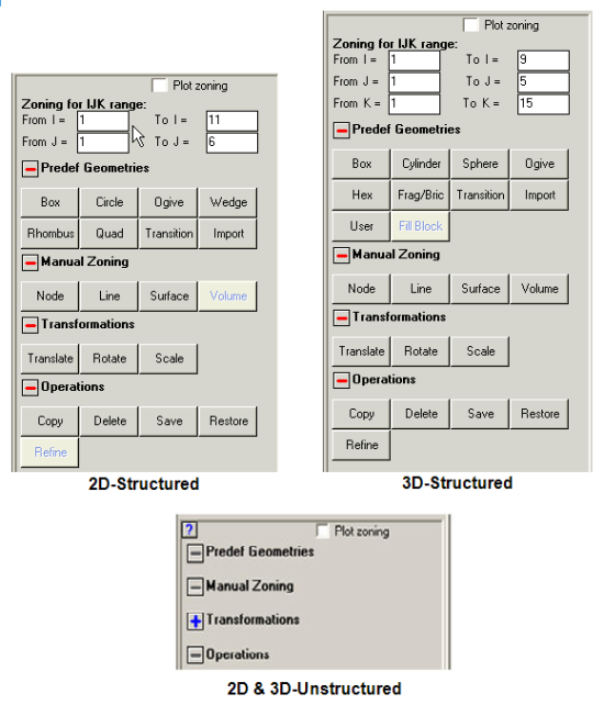
This dialog lets you define the zoning (grid coordinates) for the selected Part.
For 2D and 3D unstructured Parts the geometry and meshing cannot be defined. The only option for unstructured Parts is the Transformation option, like translation, rotation or scaling.
- Plot zoning
Standard plotting will only show elements that contain material, not unused elements.
Checking this box shows all elements, including unused elements.
- Zoning for IJK range
These fields let you specify the IJK range you want zoning operations to act on. The default values are for the entire Part.
- Predef Geometries
- Box
Zone a box.
- Cylinder
Zone a cylinder.
- Sphere
Zone a sphere.
- Ogive
Zone an ogive.
- Frag/Bric
Zone a fragment / brick wall.
- Transition
Zone a grid transition
- Import
Import zoning from an external file (.zon)
- User
Generate zoning from a user subroutine.
- Fill Block
Zone and fill an Euler-FCT grid using data from an external file.
- Manual Zoning
These options let you build a grid by specifying nodes and generating lines, surfaces and 3D volumes.
Click
 to reveal the following buttons :
 - Node
Define the coordinates of a node.
- Line
Generate coordinates along a line in index space.
- Surface
Generate the coordinates of an index plane.
- Volume
Define the coordinates within the current IJK Range.
- Transformations
These options let you translate, rotate and scale your zoning.
Click
to reveal the following buttons : - Translate
Translate zoning.
- Rotate
Rotate zoning.
- Scale
Scale zoning.
- Operations
These options let you perform various operations on your zoning.
Click
to reveal the following buttons : - Copy
Copy zoning from an existing Part to the current Part.
- Delete
Delete zoning.
- Save
Temporarily save your zoning.
- Restore
Restore zoning you have temporarily saved.