


The command language provides the capability to:
Record operations made in the user interface
Modify/Playback/repeat operations
Load operations previously saved to file
Set up models using the command language.
This feature has Beta status and you must activate it by adding the following lines above the Additional User Title option in the autodyn.ini file.
command_line_on
1
Caution: By activating this flag you accept that this is a Beta option and therefore may not be as stable or robust as expected in a general release version.
The command line is initially inactive until a model is either loaded or created. To the right of the message line there are two buttons (in addition to the Message window button) that are related to the command line.
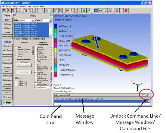
Commands can be typed directly into the command line with multiple commands being concatenated by using a ';' between the commands, i.e. PARTS:;TARGET to select a part named TARGET. Useful/help information is output to the Message/Output window. Note however that the command language is more easily used when the command window is undocked from the main user interface.
The command line creates two command files:
- autodyn.adc
This file is located in the directory C:\Documents and Settings\username\Local Settings\Temp and is overwritten every time a new Autodyn session is started.
- ident.adc
This file is created every time a new model is created. If the model is subsequently modified in a different Autodyn session the new commands are appended to this file. Therefore the ident.adc should contain all commands that have been executed on the model since it was first created.
A typical series of commands will look similar to this:
PARTS:
target
  @ZONING
  #OPERATION TYPE = Zoning
    #ZONING?= Predef
      #PREDEF GEOMETRY?= Box
        X Origin?=?0.0000000E+00
        Y Origin?=?0.0000000E+00
        Z Origin?=?0.0000000E+00
        DX?= 10.00000
        DY?= 10.00000
        DZ?= 10.00000
        #GRADING I?= NO
        #GRADING J?= NO
        #GRADING K?= NO
  @DO
  @FILL
  #OPERATION TYPE = Fill
    #FILL BY INDEX = Block
      I min?=?1
      I max?= 11
      J min?=?1
      J max?= 11
      K min?=?1
      K max?= 11
      #FILL WITH INITIAL CONDITION SET? = No
      #FILL MATERIAL? = AL 2024
      Density = 2.785000
      Int. Energy = 0.0000000E+00
      X Velocity? = 0.0000000E+00
      Y Velocity? = 0.0000000E+00
      Z Velocity? = 0.0000000E+00
      #RADIAL VELOCITY = No
      #ANGULAR VELOCITY? = No
@DO
The 'PARTS:' command word is the name
of the current command structure. (When other parts of the interface
are covered by the command line, each of the buttons on the Navigation
panel will be a command structure (that is, Materials, Boundaries,
and so on).)
The name of the part currently selected is then given, in this
case it is called 'target'. In this example the command being executed
is a zoning command followed by a fill command- @ indicates a command.
To see the current list of available commands '@?' can be typed at any time.
A # denotes an option. In the above example, #zoning enables you to choose from the list of zoning options. Typing '?#' will give you the list of options for zoning the
options are shown below:
For the example given here, predef is chosen as the option.
The predef zoning option has a sub-option '#PREDEF GEOMETRY' that enables you to choose the predef you want to zone. In this
simple example, the box predef is chosen and the required parameters
have been set.
When all the parameters have been set the '@DO' command is issued, which executes the command.
The easiest way to use the command line and become familiar with the command structure is to use the user interface to zone and fill parts as usual. The commands will then be recorded and can then be edited and played back as described above. Also, as can be seen in the picture above some guidance is given in the history window for the syntax used to set options and parameters etc. should you choose to type in the commands directly.