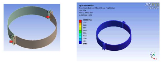
Bonded contact allows the nodes of an unstructured Part to be bonded to a face of another unstructured Part. Bonded contact alleviates the requirement that for joining purposes two nodes need to reside at the same physical location. The nodes that are to be bonded to a face may have an offset with respect to the face and the offset is a user-defined maximum physical normal distance of a node from a face which can be bonded together.
Typically the regions to be bonded are selected by face groups or parts. This means that a bond can exist in a symmetrical fashion. The algorithm will try to find a face for all the nodes in the selected groups or parts.
It is also possible to select nodal groups. The nodes in these groups will also search for an appropriate face to be bonded to. Additionally the algorithm will deduce the faces that are attached to these nodes. This facilitates the bonding of nodal groups.
During the analysis the nodes are kept at the same relative position on the face to which they are bonded. This is done by means of penalty forces which are either dependent on the mass of the nodes/faces or the stiffness of the material. The stiffness is weighted based on materials on either side of the bond. In models with mass scaling the penalty method is chosen based on the mass scaling setting:
Mass scaling off: Penalty method based on harmonic mass in the bonded pair.
Mass scaling on: Penalty method based on harmonic stiffness in the bonded pair.
| Origin of Model | Mass Scaling Off | Mass Scaling On |
|---|---|---|
| amodel_0.ad produced prior to R18.0 | Harmonic Mass | Harmonic Mass |
| amodel_0.ad produced prior to R18.0 then saved in R18.0 or later | Harmonic Mass | Harmonic Stiffness |
| amodel_0.ad produced with current release |
Note: The stiffness weighted penalty method is typically superior to a mass weighted penalty and increases the robustness of (offset) bonds. By switching on mass scaling and still using a small target timestep (eg 1e-20) no mass will be added, but the penalty method will be switched to harmonic stiffness.
When large material stiffness occurs between two materials that are bonded, it is recommended that you use an asymmetric definition where the contact scope (nodes to be bonded) refers to the soft material and the target scope (faces to bond to) refers to the stiffer material.
Bonds are allowed to fail and break upon a user-defined criterion.

- Name
Enter a name for the bonded face connection set.
- Maximum Offset
The automatic search algorithm for bonded regions will search for the minimum distance to any of the faces. If this minimum distance falls within the maximum offset value the bond pair will be established. In order to compute the proper distance to a face the algorithm will determine if the perpendicular projection to the face falls within the face, if that is not the case the perpendicular projection to the face edges is considered, if that is not the case the distance to one of the face nodes is considered. This algorithm guarantees that a minimum distance is always found and can be properly compared against the user defined Maximum Offset.
Note: In projects created before R18.0, models will still search for bonded pairs using a projection method. If these older models are saved they will start using the enhanced minimum distance search.
- Breakable
By default the bonded face connection will not be breakable. When the option Stress criteria is selected the bonded connection will fail and break upon a user-defined stress failure criterion:
Normal stress limit: maximum normal stress that can be sustained at the bond
Shear stress limit: maximum shear stress that can be sustained at the bond.
Failure of the bond occurs when:
(13–3)
where σn and σs are normal and shear stress at the bond Sn and Ss are the maximum allowed normal and shear stress limits and expn and exps are user defined exponential coefficients. The normal stress at the bond σn is nonzero for tensile values only.

- Selection method
Bonded joins can be generated in Autodyn on a part basis as well as on a (multiple) face and node group basis.
By default, the algorithm will attempt to bond all the nodes and faces in the definition in a symmetric fashion. This behavior can be changed if you define the bonds by groups. In order to facilitate anti-symmetric bonding behavior in the Autodyn system, the following naming convention can be used:
- Group Name starts with: BONDED_CONTACT-
This name indicates a contact side; all nodes in this group will be part of the node list to be bonded. None of the associated faces in this group will be a possible target for bonding.
- Group Name starts with: BONDED_TARGET-
This name indicates a target side; all the associated faces in this group will be a possible target for bonding. None of the nodes in this group will be bonded.
- Group Name starts with: BONDED_SYM-
Note that the only way to reset the behavior of a group to symmetric once the Contact and Target side names are used, is to use BONDED_SYM-.
Note:
Bonded contact is available for unstructured volume, shell, and beam elements.


