


This panel lets you join Parts of your model.
If two Parts are joined, Autodyn automatically finds and joins all coincident nodes in the two parts.
Note: Structured Lagrange elements joined to SPH nodes will not be eroded
When unstructured Parts are joined the coincident nodes can be merged into a single unstructured node. This option will increase the robustness in many applications involving joins.
Using the Bonded Face Connections option allows the nodes of an unstructured Part to be bonded to a face of another unstructured Part. Bonded contact alleviates the requirement that for joining purposes two nodes need to reside at the same physical location. The nodes that are to be bonded to a face may have an offset with respect to the face and the offset is a user-defined maximum physical normal distance of a node from a face which can be bonded together.
- Join
Joins Parts.
- Join All
Join all Parts.
- Unjoin
Unjoin Parts.
- Unjoin All
Unjoin all Parts.
- Matrix
Define join Parts using a matrix.
- Review
Review which Parts are currently joined.
- Join tolerance
Enter the tolerance you want Autodyn to use in determining which nodes should be joined. Click the Set button to set this tolerance.
The default value for the join tolerance will take care of small round-off differences in node location and will give good results. The tolerance should not artificially be increased to try to join nodes with a clear offset with respect to each other.
- Merge joined nodes
Merges joined unstructured nodes into a single unstructured node.
- Plot Joined Nodes
Check this box to plot a symbol at every joined node.
- Plot Joined Parts
Check this box to show which Parts are joined to a selected Part (a box appears to let you select a Part).
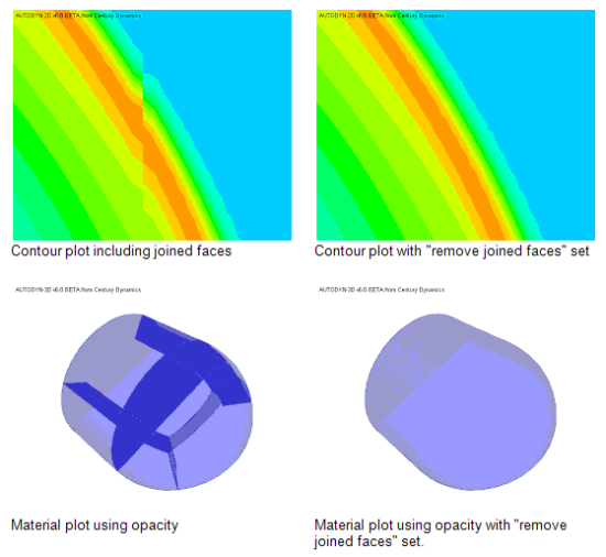
- Remove joined faces from plot
Selecting this option results in continuous contours across joined faces and also removes joined faces from other types of plots.
- Improved Rendering Across Joined Nodes
There is now an option to remove joined faces from rendered images under the Joins, Settings option. Selecting this option results in continuous contours across joined faces and also removed joined faces from other types of plots.
- Bonded Face Connections
Bonded contact allows the nodes of an unstructured Part to be bonded to a face of another unstructured Part. Bonded contact alleviates the requirement that for joining purposes two nodes need to reside at the same physical location. The nodes that are to be bonded to a face may have an offset with respect to the face and the offset is a user-defined maximum physical normal distance of a node from a face which can be bonded together.
Bonded face connections can fail and break upon a user-defined stress criterion.
- Spot Welds
Spot welds generated in an Ansys Explicit Dynamics systems are transferred to the Autodyn system as beam elements filled with a rigid material.
Spot welds utilize the multi-body rigid material option where each spot weld acts as an individual rigid boy.
Spot welds can be defined as breakable by force:
Normal force limit: maximum normal force that can be sustained by the weld
Shear force limit: maximum shear force that can be sustained by the weld.
Failure of the spot weld occurs when:

(13–1)
where f and f are normal and shear interface forces, S and S are the maximum allowed normal and shear force limits and exp
nand expsare user-defined exponential coefficients. The normal interface force f is nonzero for tensile values only.
Note that spot welds cannot be generated directly inside an Autodyn system. Spot welds should be defined in an Ansys Explicit Dynamics system and automatically transferred to a linked Autodyn system.
For each spot weld connections a multiple beam rigid body is automatically generated for each spot weld in the Ansys Explicit Dynamics system in order to guarantee the transfer of bending over the spot weld.
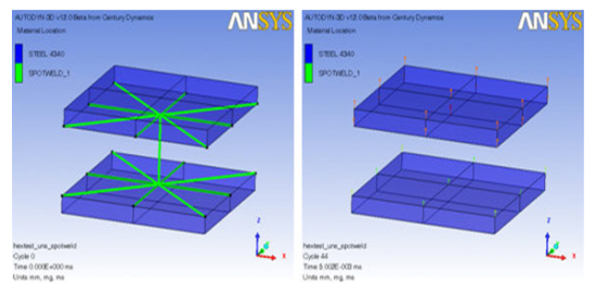
After failure of the spot weld the spot weld rigid body will be removed from the analysis model as can be seen above.
Within an Ansys Explicit Dynamics system an effective area can be input for spot welds, thus the breakable criteria can be defined in terms of stress. This stress is converted to force when transferred into Autodyn.
Spot welds of zero length are permitted. However, if such spot welds are defined as breakable the above failure is modified since local normal and shear directions cannot be defined. A modified criterion using global forces is used instead:

(13–2)
where dfx, dfy and dfz are the global force differences across the spot weld.
Note:A spot weld is equivalent to a rigid body and as such multiple nodal boundary conditions cannot be applied to spot welds.
Currently analysis models containing spot welds cannot be run in parallel.