


The Sherlock Pre and Sherlock Post systems launch Ansys Sherlock, a Java-based application that allows you to analyze the reliability of circuit card assemblies based on their design files.
For more details on working with Sherlock, see the Sherlock User's Guide.
To work through a Sherlock system workflow:
To add a Sherlock (Pre) component system, drag the system from the Toolbox to the Project Schematic or double-click the system in the Toolbox.
Add a Sherlock project to the system.
Import a Project
Right-click the Project cell and select > from the context menu.
Browse to the Sherlock project file, select it, and click .
The Sherlock GRPC console opens as the project is loading.
Create a Project in Sherlock
Right-click the Project cell and select from the context menu.
In Sherlock, in the Project menu, select .
Create a Sherlock project as described in the Sherlock User's Guide.
In Workbench, to sync the Sherlock project changes without closing Sherlock, right-click the Project cell and select from the context menu.
Note: This step is optional. When you close Sherlock, Workbench automatically syncs the project.
Save the project and close Sherlock.
Right-click the Setup cell and select from the context menu.
In the Properties pane, from the Export Type list, select the type of model to export.
From the Board list, select the board to use for the analysis.
From the Analysis Type list, select the analysis type to use.
Note: If the analysis selected is Random Vibration, set the following three options to
Yesin Mechanical, under > > :Keep Modal Results
Calculate Velocity
Calculate Acceleration
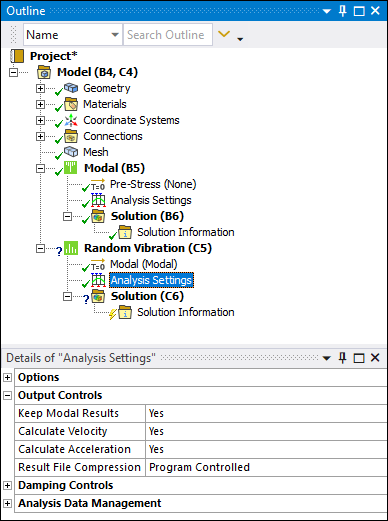
If these settings are not set correctly, the upstream Modal system's data is not transferred to the Sherlock (Post) system.
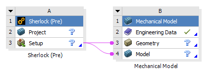
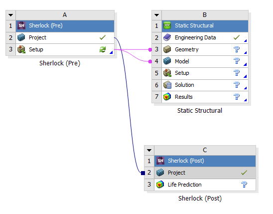
Right-click the Setup cell and select one of the following options from the context menu.
>
A Mechanical Model system is added to the Project Schematic.
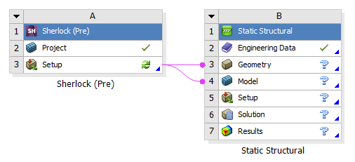
>
A Mechanical system corresponding to the analysis type selected in the previous step is added to the Project Schematic.
>
A Mechanical Model system and a Mechanical system corresponding to the analysis type selected in the previous step are added to the Project Schematic.
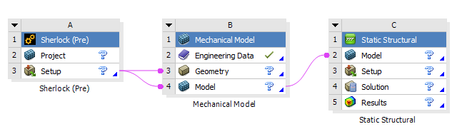
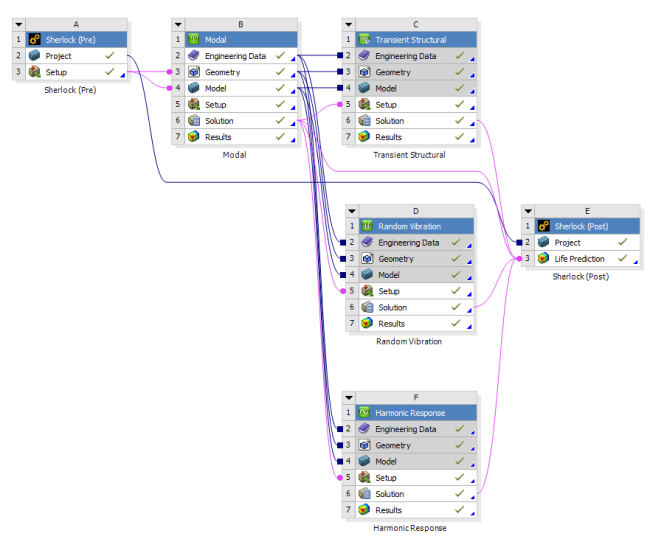
For multi-assembly projects, you can add other systems to the Project Schematic as required.
An example multi-assembly project is shown in the following image.
Note: When you want to use the same base Sherlock project with different analysis or different boards, create the project in the Sherlock (Pre) system and then duplicate it. Use the Properties fields of each copy of the system to set up one analysis.
Drag a Sherlock (Post) system from the Toolbox and drop it onto the Project cell of the Sherlock (Pre) system
Drag the Solution cell of the Mechanical system onto the Life Protection cell of the Sherlock (Post) system.

Right-click the Setup cell of the Sherlock (Pre) system and select from the context menu.
Right-click the Geometry cell of the Mechanical system and select from the context menu.
To view the Mechanical system geometry, right-click the Model cell and select from the context menu or double-click the Model cell.
Alternatively, you can complete this step using the Setup cell.
In the Mechanical application window, complete your analysis using the application's tools and features.
Right-click the Project cell of the Sherlock (Post) system and select from the context menu.
Right-click the Life Prediction cell of the Sherlock (Post) system and select from the context menu.
The Sherlock GRPC console opens as the cell is updating.
Right-click the Life Prediction cell and select from the context menu.
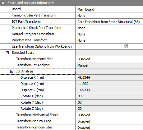
To set the transform options on a board directly from Workbench:
Select the check box.
Select a Board from the list.
For each analysis type, select one of the following options:
Setup Description Disabled No transformation.
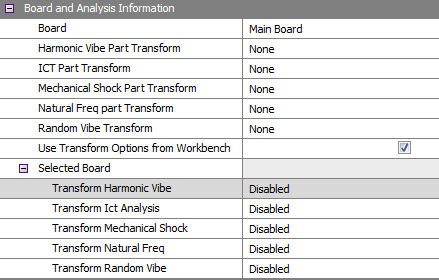
Enabled Sherlock determines transforms automatically.
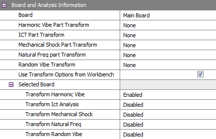
Manual Set the transformation numbers manually.
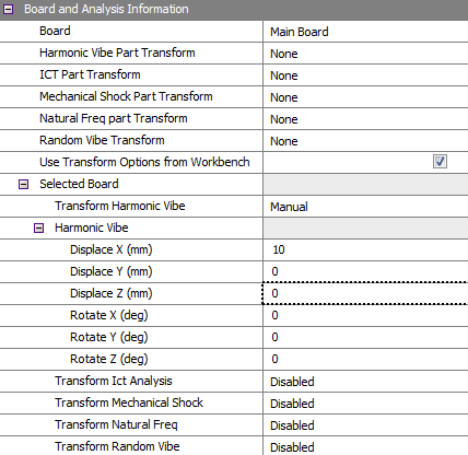
From Mechanical Import the transformation numbers from the Solution cell of the Mechanical system.
 Note:
Note:If the Mechanical solution is updated in the Mechanical editor, you must update the Solution cell in Workbench before the updated transform numbers are applied to the Sherlock (Post) system.
If the Mechanical solution is already up-to-date and is not connected to the Sherlock (Post) system, the transform numbers will not appear when you connect the systems. You must complete a solution update to see the numbers in the Sherlock (Post) system.
Select the appropriate Life Cycle events from the available lists.
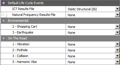
Note:The available Life Cycle events depend on what is created in the Sherlock project. They are also filtered by the analysis systems connected to the Sherlock (Post) system.
If you have an older Workbench project created before 2022 R2, right-click the Project cell of the Sherlock (Pre) system and select from the context menu to open Sherlock and pull in the new mappings.
For more details on Sherlock Life Cycles, see Project Life Cycles in the Sherlock User's Guide.
To view the 2D or 3D results in Sherlock, right-click the Life Prediction cell and select one of the following options from the context menu:
Note: The Sherlock 3D Viewer may run slowly when analyzing large projects even if the computer has ample amounts of memory. This is likely a Java issue.
If you encounter an error message that the 3D Viewer has run out of memory, you can allocate more memory to the 3D Viewer in the Launcher Settings. From Sherlock's Main Menu, click > . Refer to Launcher Settings for additional information.