You can access Sherlock Settings by clicking Settings on the Main Menu and then selecting any of the listed entries.
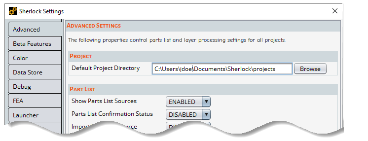
The Advanced Settings dialog has several sections, each explained below.
Project
| Default Project Directory: Select the default directory where Sherlock projects are saved. |

Part List
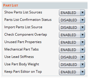
| Show Parts List Sources: When ENABLED, Part Property sources will be displayed in the Parts List and the Part Editor. See Part Source Priority. |
| Parts List Confirmation Status: When ENABLED, the confirmation status of a part's properties is displayed in the parts list. See Confirming Parts. |
| Import Parts List Source: When ENABLED, you will have the option to prioritize the source of the imported part properties as User instead of BOM in the Parts List Import dialog. See Importing the Parts List. |
| Check Component Overlap: When ENABLED, Sherlock will display a warning when it detects overlapping components in a circuit card assembly. |
| Unused Part Properties: This setting affects how the Part Properties Viewer and Editor display properties that are not applicable to a selected part. When ENABLED (default), these unused properties are displayed and editable. Select DISABLED if you want unused part properties to remain visible but not editable. Select HIDDEN to hide unused part properties altogether. See Part Property Viewing/Editing Options for more information. |
| Mechanical Part Tabs: When ENABLED, all Part Editor tabs are enabled for Mechanical Part component types. |
| Show Lead Stiffness: When ENABLED, Lead Stiffness will be displayed in the Part Properties Viewer and the Part Editor. (See Managing Part Properties and The Part Editor.) See also the lead stiffness entry in Sherlock Part Properties. |
| Show Part Body Weight: When ENABLED, Sherlock will display part body weight in the Part Editor and use it in FEA analysis. If this property is not displayed, Sherlock will automatically compute the weight. |
| Keep Part Editor on Top: When ENABLED, all open Part Editor and Viewer dialogs remain on top of the main Sherlock application window. |
Layer
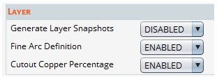
| Generate Layer Snapshots: This feature (when ENABLED) generates image snapshots when importing layers. This improves Layer Viewer performance, but it may reduce the resolution of large layer models. |
| Fine Arc Definition: When ENABLED, Sherlock generates smoother arcs definitions when converting Gerber, ODB++, and IPC-2581 files. |
| Cutout Copper Percentage: Enabling this setting will subtract the area of cutouts from the total PCB area when Sherlock computes the copper percentage of a layer. |
Life Cycle

| Unsaved Results Alert: When ENABLED, Sherlock will display an alert if you are in danger of losing unsaved analyses when you choose to apply Life Cycle changes. |
General
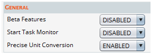
| Beta Features: When ENABLED, the Beta Features tab appears in the Sherlock Settings window. See below, Beta Features Settings. |
| Start Task Monitor: When ENABLED, the Sherlock task monitor will open automatically when the Sherlock application launches. |
| Precise Unit Conversion: When enabled, Sherlock uses more precise methods of performing unit conversions. This may result in slower file processing and analysis. |
Trace Modeling
| See Advanced Trace Modeling Settings for details on this section of the Advanced Settings dialog. |
By default, the Beta Features tab is not displayed in the Sherlock Settings window. To activate the tab, do the following: In the Sherlock Settings window, click the Advanced tab. Then under General, select ENABLED for Beta Features (see above).
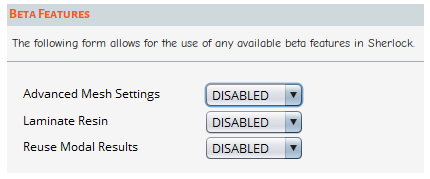
The Beta Features panel allows you to enable or disable individual beta features available in Sherlock.
Warning: Before enabling any beta feature, read the Beta Features Disclaimer.
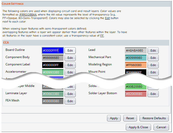
The Color Settings affect how circuit card and result layers are displayed. These settings can be configured with the color of your choosing. Color values are formatted as #RRGGBBAA, where AA represents the level of transparency (FF=Opaque, 80= Semi- Transparent). Colors may also be selected by clicking the Edit button next to each color.
Note: Transparency settings and the Layer Viewer: When objects are defined with semi-transparent colors and they overlap within the same layer, they will appear darker than other layer objects. If you prefer that all layer objects have a consistent color, use a transparency value of FF (opaque).
Use the buttons in the dialog to save or restore settings:
Apply: Applies and saves changes to color assignments.
Reset: Resets color assignments to their last saved values.
Restore Defaults: Restores color assignments to default values. When you click the Restore Defaults button, Sherlock will prompt you to confirm your decision. If you click Yes, all color assignments will return to their default settings. Once confirmed, this action cannot be undone.
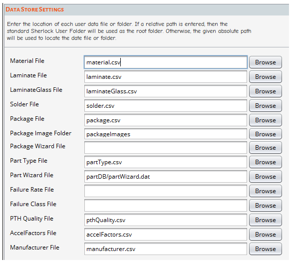
The Data Store Settings control the location of each user data file or folder. If a relative path is entered, the standard Sherlock User Folder will be used as the root folder. Otherwise, the specified absolute path will be used to locate the data file or folder.
The user data files or folders listed in the Data Store Settings are: the Material File, Laminate File, LaminateGlass File, Solder File, Package File, Package Image Folder, Part Type File, Part Wizard File, PTH Quality File, AccelFactors File, Manufacturer File, and the Meshed Part Folder.
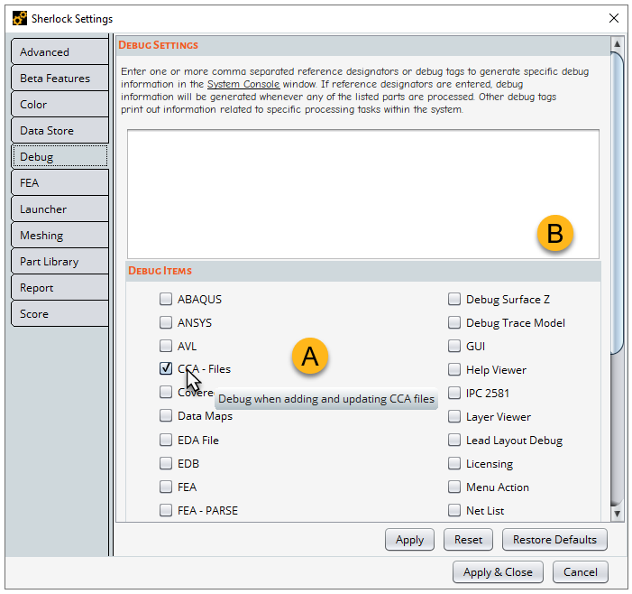
The Debug Settings window allows you to activate debug tags which generate debugging information in Sherlock's Client Console. The tags are listed in the Debug Items panel (A, below). Hover over a tag to see a tool tip that briefly explains its function. To activate a tag, click the appropriate check box and click the Apply or Apply & Close button.
The text field (B, below) serves a couple of functions: You can manually enter a debug tag not listed on the Debug Items panel. Also, you can have Sherlock generate debugging information for a specific part. Simply enter its Reference Designator in the text field. Separate multiple entries with a comma. Sherlock will provide details about the component(s) in the Console during an FEA or Solder Fatigue analysis.
For a detailed explanation, see FEA Analysis Settings.
The Launcher Settings are used when launching Sherlock. Any setting changes will take effect the next time the application is launched.
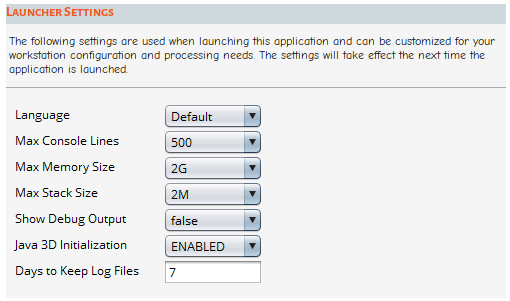
| Language: Select the language used in the application. Sherlock is currently supported in English, Japanese, and Korean. See limitation below. |
Limitation: The language fonts in Sherlock do not support one another. For example, if you name a project using Japanese characters and then change the Language to English, the Japanese characters will not be visible, and the resulting text will not be correct.
| Max Console Lines: Specify the maximum number of lines to retain in the Console. |
| Max Memory Size: Specify the maximum amount of memory Sherlock uses for processing. These settings apply also to Sherlock's 3D Viewer and the Results Viewer clients. The settings do not affect memory usage at start-up, however, but only during high-demand processing as needed. Remember, you must restart Sherlock for any changes to take effect. For specific information on memory usage during FEA process, see FEA Processing. |
| Max Stack Size: Specify the maximum Java stack size. Typically, this setting does not need adjusting. |
| Show Debug Output: This enables additional application debug messages to be displayed on the Sherlock Console. |
| Java 3D Initialization: When DISABLED, Sherlock will not initialize the 3D system prior to needing it. Leaving it ENABLED reduces the initial startup time when using the Part Editor and Viewer. This should only be DISABLED if Sherlock generates a "GDI Generic Driver use detected" message. |
| Days to Keep Log Files: Sets the number of days Sherlock preserves the log files. |
To access the Mesh Settings within Sherlock, select from the main menu.
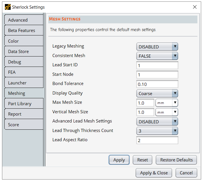
Legacy Meshing: By default, Sherlock uses Ansys Meshing (Bonded). If you set Legacy Meshing to ENABLED, you have the option of using Sherlock's legacy meshing (Merged) when configuring a model for Finite Element Analysis.
Consistent Mesh: When ENABLED, Sherlock generates the same mesh for a given circuit card when meshing parameters and geometry are unchanged.
Lead Start ID: This value sets the ID of the first lead in the FEA Model. Lead Start ID does not affect the mesh. It only impacts the numbering of the node. The default value is 1.
Start Node: This value sets the ID of the first node in the FEA Model. Start Node does not affect the mesh. It only impacts the numbering of the node. The default value is 1.
Bond Tolerance: Sherlock uses Constraint Equations (CE) to establish bonded contacts. This value sets the bond tolerance in mm when generating FEA bonds. The default value is 0.10 mm.
Display Quality: This option sets the display quality of the 2D Graphical Result Layers. Options include Coarse and Fine. When Coarse is selected, each triangular or quad face in the mesh will be rendered using a single color representing the average of the three or four corner values. The Fine setting results in smoother edges between colored regions by using smaller triangles and quads using the midpoint method. This setting has no effect on the FEA results. It simply changes the appearance of the 2D Results Layer. The default is Coarse. See Graphical Result Layers to see how Display Quality affects the 2D Graphical Result Layers.
Max Mesh Size: This value sets the default mesh size, indicating the maximum length and width of an element. This setting is only used if there are no values in the analysis mesh settings.
Vertical Mesh Size: Sets the default vertical mesh size. This setting is only used if there are no values in the analysis mesh settings.
Advanced Lead Mesh Settings: When ENABLED, the Advanced Lead Mesh Settings give you more options for modeling leads such as the ability to specify how many elements define the thickness and width of the lead. Once enabled, Sherlock applies the ALM settings to the model when generating the 3D FEA model, when running an FE analysis, or when generating a 3D model of a component in the Part Viewer/Editor. Enabling this feature increases processing time, however. By default, Advanced Lead Meshing is DISABLED. For a detailed explanation of Advanced Lead Meshing, see Advanced Lead Meshing.
Lead Through Thickness Count: The setting applies only when Advanced Lead Mesh Settings is enabled. It sets the number of elements through the lead thickness and width when Sherlock models a lead. The default value is three, and the maximum is five. See note below.
Lead Aspect Ratio: The setting applies only when Advanced Lead Mesh Settings is enabled. When Sherlock generates a lead model, the Lead Aspect Ratio (LAR) determines the ratio between the elements' thickness and height. The default value for the LAR is two and the maximum is ten. See note below.
Note: You can also set the Lead Through Thickness Count and the Lead Aspect Ratio in the Lead Modeling tab of the Analysis Properties window when setting up your FE analysis. Until you run your first analysis with Advanced Lead Meshing enabled, Sherlock defaults to the values you have chosen in the Sherlock Settings window. For a more detailed explanation of Advanced Lead Meshing and guidance on choosing optimal settings, see Advanced Lead Meshing.
Here you can specify the name and location of the folder where the library data is stored. If the specified folder does not exist and Read Only is NO, then a database folder will be automatically created.

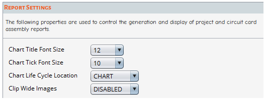
The Report Settings control how project and circuit card assembly reports are displayed. See Generating Report Files.
| Chart Title Font Size: This value specifies the font size used in chart titles. |
| Chart Tick Font Size: This value specifies the font size used in chart axis labels. |
| Chart Life Cycle Location: This value specifies the location of the service life goal in life prediction charts. Options include CHART or SUBTITLE. |
| Clip Wide Images: DISABLED by default. When ENABLED, Sherlock clips Layer images that are wider than their height to preserve space. |
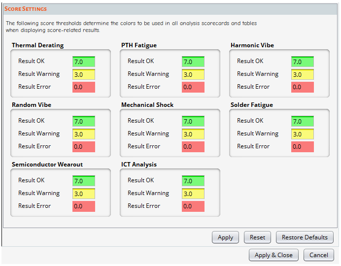
Use the Score Settings dialog to set threshold levels for score-related results. The thresholds you can customize are Result OK, Result Warning, and Result Error which correspond to Green, Yellow, and Red respectively. You can see a sample score card here.
Score Settings apply to the following analyses: Thermal Derating, PTH Fatigue, Harmonic Vibration, Random Vibration, Mechanical Shock, Solder Fatigue, Semiconductor Wearout, and ICT Analysis.
