


After introducing a new Mechanical analysis system to the Project Schematic and assigning an appropriate name, the focus is typically directed to the Geometry cell, because this is usually the first cell in the system that requires user input. You can edit or define material models in the Engineering Data cell, but this example assumes that the default materials are sufficient.
Important: You are not required to define a geometry. You can open Mechanical without an attached geometry. You can simply skip the step of specifying a geometry and open Mechanical. This can be done to create a template for use with multiple geometries. Moreover, you are not required to define an analysis system. You can begin your simulation with a Mechanical Model system and build the simulation as desired until you wish to add a geometry as well as specify an analysis type. This flexibility can be beneficial.
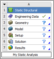
You typically work through the system from top to bottom. Use the context menus for each cell to view and select operations that can be performed for that cell.
Import or create a geometry:
To import an existing geometry, right-click the Geometry cell and select . From the context menu, select a previously used geometry, an active CAD model, or browse to a desired folder location.
To create a new geometry, select or , as appropriate.
To define all loads and boundary conditions, right-click the Setup cell and select .
Mechanical opens. Set up your analysis using the application's tools and features.
Typically, you solve your analysis from within Mechanical, however, you can right-click the Solution cell and select . The results appear automatically.
For more information on setting up and running specific Mechanical analyses, see Analysis Systems.