


After introducing a new Fluid Flow analysis system to the project schematic and assigning it an appropriate name, the focus is typically directed to the Geometry cell, because this is usually the first cell in the system that requires user input. An example of both a CFX and a Fluent fluid flow system is shown below.
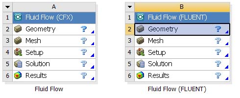
You typically work through the system from top to bottom. Use the context menus for each cell to view and select operations that can be performed for that cell. For fluid flow systems, the process is somewhat flexible; you can start from geometry, from an existing mesh, or from an existing case file; each is described in the following sections.