


If it will be advantageous to run an FSI problem as a coupled analysis, then the recommended approach is to build up to the final analysis in stages of progressive complexity. This section takes the generalized process described in Building Up to a Coupled Analysis and applies it to the incremental creation of a two-way coupled FSI analysis.
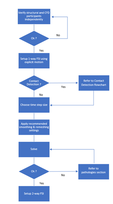
The procedure for building a coupled analysis is summarized below in Figure 74: Workflow to set up a coupled FSI analysis.
Note: In the following sections, the structural solver is assumed to be Ansys Mechanical. The fluid solver may be any Ansys CFD solver that supports System Coupling FSI simulations.
Because the constituent fluid and structural problems may each be quite complex on their own, ensure that they can each be solved individually before attempting to join them in a coupled analysis. Solve the problems independently, as follows:
- Fluid analysis:
Solve only for the fluid-flow part of the problem (that is, do not solve for mesh motion).
To set up the fluid-flow analysis:
Remove any System Coupling motion specifications that would be used to verify mesh motion and remeshing in the fluid analysis.
Introduce the initial and boundary conditions.
Define a motion (structural displacement) as an input. This should approximate the motion (or range of motion) expected from the structural problem.
- Structural analysis:
Solve only for the explicit motion and preliminary contact (with no offset) part of the problem (that is, do not solve for fluid force).
To set up the structural analysis:
Remove any System Coupling motion specifications (if they exist) that would be used to verify mesh motion and remeshing in the fluid analysis.
Introduce the initial and boundary conditions.
If applicable, add contact and contact offsets to ensure that the fluid mesh does not collapse.
Define a load (fluid force) as an input. This should approximate the load (magnitude and distribution) expected from the fluid analysis.
Once you have verified that each of the individual problems can be solved successfully on its own, you can incorporate them into a series of one-way coupled analyses.
In this step, incrementally add complexity and non-linearity by setting up and solving each problem as a one-way coupled analysis.
Set up and run two one-way coupled analyses with a structural source participant and a fluid target participant, where the displacement data generated by the structural analysis is applied to the fluid analysis. Solve for the motion transfer, first without and then with fluid-flow calculations.
- Analysis 1: Motion transfer to fluid (without solving flow equations)
First, solve for the transfer of motion from the structural analysis to the fluid analysis, but without solving the flow equations. This allows you to test mesh motion and remeshing. It can help you to identify and address issues that cause mesh folding, as well as to determine contact offsets and timescales.
To set up the analysis without flow equations:
Remove the approximated motion input that was applied in the individual fluid analysis.
Add System Coupling mesh motion to the analysis.
For the fluid side of the analysis, configure mesh motion and deformation settings. If applicable, set contact detection parameters.
For the structural side of the analysis, configure contact offsets to address limitations in the fluid analysis.
Generate System Coupling files.
If using one of System Coupling user interfaces, generate a System Coupling Participant (.scp) file for each participant.
If using System Coupling in Workbench, generate a System Coupling Input (.sci) file for the analysis.
Note: You can export a Workbench-based coupled analysis for execution in one of System Coupling's user interfaces. For details, see Exporting a System Coupling Setup.
Complete the coupled analysis setup (duration, coupling steps, coupling iterations, and so on) according to the System Coupling context being used.
When this analysis has been successfully solved, move on to solving the analysis with flow equations.
- Analysis 2: Motion transfer to fluid (with solving flow equations)
Next, expand on the previous one-way analysis, this time activating the flow equations so that they will be solved with the transfer of motion from structural analysis. This allows you to verify that the flow equations can still be solved after the introduction of motion to the analysis.
To set up the analysis with flow equations:
Remove the results from the individual structural analysis.
Activate flow equations for the fluid analysis.
Regenerate the System Coupling files to capture the changes to the participant physics, as described previously for Analysis 1.
Once the one-way fluid analysis has been solved with flow equations, how you proceed depends on your end goal for the problem:
If a one-way coupled analysis is your end goal, then the next step is to evaluate its convergence. For information on assessing coupled analysis convergence, see Evaluating Convergence and Data Transfer Accuracy. To evaluate participant convergence, use the method provided by the CFD solver.
If a two-way coupled analysis is your end goal (or if you observe significant deformation of the fluid domain because of the structural motion), then proceed to the creation of the two-way analysis.
Note: Before doing so, ensure that you have also completed the intermediate step of solving the structural problem as a one-way coupled analysis.
Solve for the transfer of Force from the fluid analysis to the structural analysis as a one-way coupled analysis by adding coupling specifications to the problem. This allows you to verify that the structural equations can still be solved after the introduction of applied force to the analysis.
Additionally, in setting up and running the one-way analysis, you may be able to identify and address potential issues regarding timescales, mesh folding, maximum stress values, and special solution considerations (for example, mixed u-P formulation for nearly incompressible hyperelastic solids).
- Force transfer to structural
When setting up the one-way structural analysis:
Remove the approximated load that was applied in the individual structural analysis.
Add a System Coupling Region to the analysis.
Suppress the displacement data transfer so that the analysis is one-way.
Generate System Coupling files.
If using one of System Coupling user interfaces, generate a System Coupling Participant (.scp) file for each participant.
If using System Coupling in Workbench, generate a System Coupling Input (.sci) file for the analysis.
Note: You can export a Workbench-based coupled analysis for execution in one of System Coupling's user interfaces. For details, see Exporting a System Coupling Setup.
Complete the coupled analysis setup (duration, coupling steps, coupling iterations, and so on) according to the System Coupling context being used.
Once the one-way structural analysis has been solved, how you proceed depends on your end goal for the problem:
If a one-way coupled analysis is your end goal, then the next step is to evaluate its convergence. For details on assessing coupled analysis convergence, see Evaluating Convergence and Data Transfer Accuracy. To evaluate participant convergence, use the method provided by the structural solver.
If a two-way coupled analysis is your end goal (or if you observe a significant structural deformation because of the applied load), then proceed to the creation of the two-way analysis.
Note: Before doing so, ensure that you have also completed the intermediate step of solving the fluid problem as a one-way coupled analysis.
Solve the fluid and structural problems as a two-way coupled analysis.
When setting up the two-way simulation:
For the fluid analysis, remove the initial structural displacement input that was applied to approximate the expected motion. This allows the actual displacement data generated by the structural analysis to be calculated and applied to the fluid analysis.
For the structural analysis, remove the initial fluid-force load (explicit displacement) that was applied to approximate the expected load. This allows the force data generated by the fluid to be calculated (once the transport equations are solved) and applied to the structural analysis.
Incorporate each participant problem into the two-way simulation.