


Creating Custom Symbols
A custom symbol is a two dimensional collection of sketch curves and text grouped together as one selectable and editable entity. Your symbols can include anything drawn with Sketch tools and text made with the Note tool.
-
Click
 Create in
the Symbols group on the
Detail tab.
The Symbol tab will open in the ribbon bar.
Create in
the Symbols group on the
Detail tab.
The Symbol tab will open in the ribbon bar. -
Use the following tools in the Symbol
tab to build your custom symbol:
Select: This tool is active by default. Use it to select sketch curves and text to include in your symbol.
Editable Text: Use this tool to select notes that will be editable when you use the symbol. Notes you select with the Select tool cannot be edited in the finished symbol.
Remove: Use this tool to remove elements from the symbol.
Leader Attachment: Use the Horizontal or Vertical tools to add note leader attachment points to the symbol. Click to add a note leader, then drag the leader into position. You can drag the white circle or the red diamond to adjust the leader's length.
You can create note leaders that are attached at these positions. The line segment between the white circle and the red diamond is fixed. The line segment after the red diamond is adjusted when you add the leader.
Use original style in inserts: Use the original text height for inserted symbols.
Scale symbol to text height: Select this option if you want to set the reference text height that is used if you scale the symbol based on text height when it is inserted. The ratio between the current window text height and the symbol reference text height determines the scale of the symbol. If you select this option you can also change the Reference text height.
Symbol Space: These options determine how the symbol is scaled in your design.
Model space: Select this option if you want the symbol to remain the same size when you change the scale (in the Sheet Setup group on the Detail tab).
View space: Select this option if you want the symbol to be resized when you change the scale.
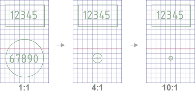
The example below shows two symbols scaled at 1:1, 4:1, and 10:1. The rectangular symbol was set to Model space and the round symbol was set to View space.
-
If you want the symbol to be attachable, move the origin handle
(shown below) to set the origin of the symbol and then
select one or more Placement options
to determine how the symbol will be scaled in your
design:
Allow attaching placements to geometry: Attaches the origin point of the symbol to 3D edges and curves. You must select this option to create an attachable symbol.
Orient placements normal to geometry: Orients the symbol perpendicular to the selected curve or face.
Maintain an upward orientation for placements: Automatically positions a symbol oriented normal to geometry so that it is never upside down. This option is useful for annotation symbols, such as surface finishes, that should be perpendicular to their reference geometry and also right side up relative to the reading direction of the model.

When you select the first two options, the symbol is automatically oriented perpendicular to the reference.