


Using a Bend Deduction Table
Bend deduction tables are used to calculate flat pattern layouts. The tables are based on the Bend Deduction (BD) formula, which calculates the flat line length to produce a specific bend angle.
BD = 2 X OSSB - BA
Where:
- BD is Bend Deduction
- BA is the Bend Allowance that equals the arc length of the bend along the neutral line. The neutral line is the radius where the material transitions from compressive stress (inside) to tensile stress (outside)
- OSSB is the Outside Set Back. Depending on the bend angle, SpaceClaim uses two different definitions of OSSB as explained below.
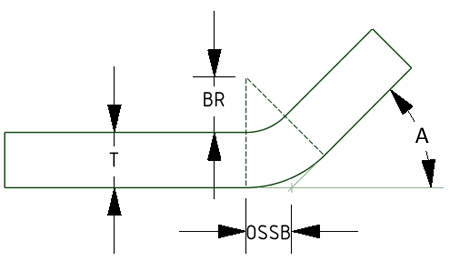
For bend angles less than 90-degrees, OSSB is measured from the beginning of the bend to the Outside Mold Line, which is the intersection of the planar faces. See the image below.
|
OSSB = Tan(A/2) X (BR + T) Hence BD = 2 X Tan(A/2) X (BR + T) - BA Where:
|
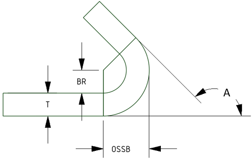
For bend angles greater than, or equal to, 90-degrees, the OSSB is measured from the beginning of the bend to a plane tangent to the outside bend face. This means that the OSSB is the same as the outside radius of the bend. See the image below.
|
OSSB = BR + T Hence BD = 2 X (BR + T) - BA Where:
|
- If a bend table is not assigned to a part, the Bend Allowance is calculated from the default K-factor found in the Sheet Metal options.
- If a bend table is assigned to a part, the Bend Allowance is obtained from the table and the assigned bend table file must specify tables for all possible combinations of part thickness and Vee Die width.
- If some bends in the part use Vee Die and other bends in the part do Not, the assigned bend table file must specify a table with no Vee Die Width entry.
- If you enter values in the Properties panel for a Bend Allowance or Bend Deduction, it will override the values obtained from the bend table or computed using K-factor.
- You can set the bend deduction to a negative value to correctly represent the corresponding bend allowance.
A bend table can also be assigned to the part. All values may then be obtained from the bend table instead of being calculated. Any values not obtained from the bend table may result in an error when you unfold the design. You can clear the sheet metal bend table assignment from a component by selecting the blank value from the Bend Table property drop-down.
The table below shows a simple bend table as it would appear in a spreadsheet editor. Keywords are shown in bold. Angle Values are measured from the flat.
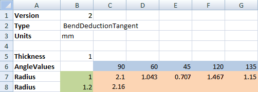
When you unfold a sheet metal design, the thickness, inner bend radius, and angle from the design are used to determine the value in the selected table.
Once you select a bend table, you can edit the Vee Die Width property in the Properties panel. Vee die width sets the width of the tooling that produces the bend.
To use a sheet metal bend table to calculate unfolded lengths, you can use an existing file or create a custom file. To use an existing file, select a sheet metal component and change the bend table property in the properties panel. To use a custom file, do the following:
Copy the
Sample.csvfile in the installation directory>/Library/Bends folder where installation directory>is where you installed the software or into a SpaceClaim Support File directory.- Paste it into the same directory and give it a new name.
- Edit the file as described below in the Comma-separated value file section.
Select the component and change it's Bend Table property for the new custom file.