


Calculating Bend Allowances
Bend allowance calculations use what is known as a K-factor. This is the ratio of the location of the neutral line (t in the image below) to the material thickness (T). When metal is bent, the material at the inside radius is put in a compressive state while the material at the outside radius is put in tension. The neutral line is the point of zero stress where the material transitions from compression to tension.
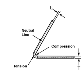
K-factor = t/T
The K-factor is a geometric calculation and does not take into account physical factors for a given bend process (material type, bend operation type, tools, etc.). Because of this, the only way to know the actual K-factor for a given setup is to do a reverse calculation from an actual bend. In other words, bend the metal, measure the result, and calculate the K-factor.
SpaceClaim determines the correct K-factor curve so you have a more accurate result, without changing the K-factor or frequently change bend tables. The default bend allowance produces an accurate result for normal bends made with normal tools and a normal press brake. For basic parts, you should use the default allowances. For special cases, you can use a bend allowance table.
The curve for the default values used in SpaceClaim is shown below.
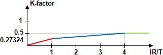
The graph shows three segments: red, blue and green.
- The red segment represents bend radii less than the material thickness. Because of the physical limit of the steel compressibility, it is difficult to obtain bends with a radius less than the thickness in an air bend process.
- The blue segment shows that, as the inner radius increases, the K factor is not constant. It increases up to approximately 0.5 when the inner radiu is about four times the material thickness. It does not increase beyond that because the material is no longer stretched. A K-factor greater than 0.5 is not possible.
- The green segment is constant at 0.5, which is the neutral axis for bends with a radius greater than four times material thickness.
The point where the red and blue segments meet is important. It represents a bend radius equal to the material thickness. For normal bends, a reverse calculation finds the K-factor to be:
K = (4-PI) / PI = 0.27324
This can be confirmed by press brake manufacturers. It is correct for normal bends because it is based on the actual physical result.
You can build bend allowance tables for your materials and processes. When your tables are filled (which is a one-time task), you can unfold with the tables, or use the default value.
With a sheet metal design selected at the top level of the Structure tree, theK-Factor Typeoption displays in the Sheet Metalgroup of thePropertiespanel. By default, the K-factor type is set to Variable, but you can also set a constant K-factor.
The Constant K-Factor type option allows you to enter a numerical value for the part. Using this option, you can map the design to other mainstream CAD functionality, or, adjust the design to a manufacturer's unique standards or tolerance levels to achieve various unfolding results.