Click the arrow under Dimension in the Annotation group on the Detailing tab
and select Ordinate
Dimensions.
If you are creating a dimension in 3D, click a face to create the plane on
which to place the dimension.
Mouse over the faces of your design to preview the eligible annotation
planes. (In Sketch and Section mode, the sketch grid defines the annotation
plane.) If multiple objects occur at your cursor location, use the scroll
wheel or arrow keys to highlight each one.
To create an annotation plane for a cylindrical face, select the cylinder's
axis.
If you need to change the annotation plane, right-click and click
Select New Annotation Plane from the context menu.
Then right-click the new place and click Set As Annotation
Plane.
Click a line, edge, or Center Line to set the baseline dimension.
You can use an existing extension line as a dimensioning reference. An
extension line is the line that connects the point to the dimension text. If you
select an extension line, the baseline dimension for the extension line's
dimension is used.
Hover over the face to see all the possible dimensions.
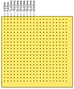
In cases with many ordinate dimensions, the preview may be slow. Start SpaceClaim using the following command line option to
limit the number of dimensions that are shown in the preview. The example
specifies '10' but you can set it to any number you wish.
MaxOrdDims=10
The plate shown below has 400 holes but only 10 are shown in the preview.
Click a point to place the dimension line.
If you select a face, all of the possible ordinate dimensions will be
created.
You can click multiple points to use the same baseline for those
dimensions.
The baseline dimension (0) is displayed or hidden
based on which detailing standard is selected in the Detailing options.
Automatic jog points are included if ordinate dimensions are too closely
spaced. This helps make them easier to read.
Example:
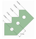
Using an Angled Baseline
First, establish a simple, oriented dimension. Then use one of the witness lines to
set the baseline and orientation of the ordinate dimensions.
In this example, the leftmost witness line of the existing circle-to-circle dimension
was selected to define the baseline.


 Dimension in the Annotation group on the Detailing tab
and select
Dimension in the Annotation group on the Detailing tab
and select  Ordinate
Dimensions.
Ordinate
Dimensions.