


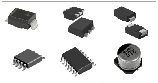
A variety of part types and package styles use leads that extends out from the side or bottom of the package body which are soldered to the PCB. These leads offer some compliance to the solder joint, meaning that in general leaded parts have improved thermal cycling solder fatigue performance.
| ID Tab |
|
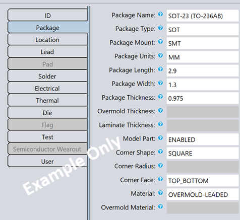
SMT Leaded Part Properties:
| Package Tab |
|
Tip: The content below assumes you are using Sherlock's default lead modeling. If you have enabled Advanced Lead Meshing, refer to Advanced Lead Meshing in the Sherlock User's Guide for additional information on how lead properties are defined.
Most lead geometry inputs are clearly stated on the data sheet. The sections below explain the various dimensions Sherlock requires for each lead type. You can also find this information in the following places:
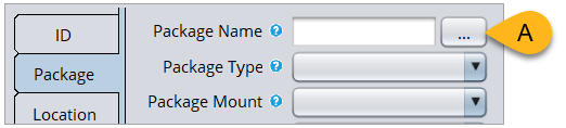
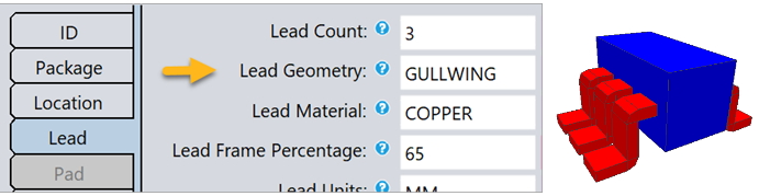
Click the blue question mark in the Part Properties Editor to view the Tool Tip as shown in the image below.
See Surface Mount Lead Modeling in the Sherlock User's Guide.

| Lead Tab |
|
Tip: You will find Lead Frame Percentage among the Lead properties for SMTs. This is the percentage of lead material in the layer of the package beneath the die. It is only used when exporting a project to Ansys Electronics Desktop for thermal conductivity calculations.
|

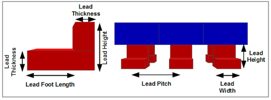
Lead geometry subsections:
Lead Height: If not provided by the data sheet, use this approximation: half the package thickness plus the standoff.

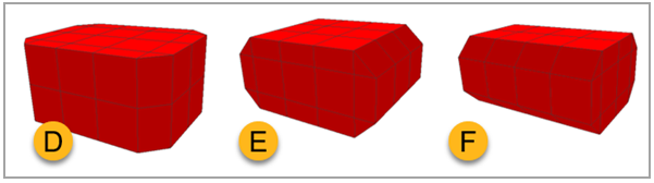
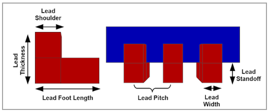
Sherlock models C and J leads using the same basic elements (Shoulder, Leg, and Foot for example) in the same relative arrangement, with the Foot tucked back under the part. In practice, C leads usually have equal Shoulder and Foot lengths (C, below), whereas the Foot is usually longer than the Shoulder in J leads (J, below). In the real world, J leads also have a toe that curls toward the bottom of the part, but for simplicity and ease of modeling, Sherlock ignores the toe when modeling the J lead. The following diagram depicts how each of the lead properties are used by Sherlock to construct a C_Lead or J_Lead model.

When incorporated into the FEA model, each C or J lead is bonded to the part using the side Shoulder face and bonded to the PCB using the bottom Foot face.
Lead Height is measured from the Foot of the Lead to the center of the Lead Thickness at the shoulder.
Lead Height: If the mechanical drawing does not provide this, use the following formula:
Lead Height = Lead Standoff + 0.5(Package Thickness) Lead Shoulder and Lead Standoff: Leads are often molded into a package body or closely folded around it. In those cases, you can set the Lead Shoulder and Lead Standoff to a small nominal value of
0.1.Lead Standoff = Lead Thickness
 |
Tip: Lead height is often not given for L-Leads, particularly for V-Chip electrolytic capacitors. In these cases, 1 mm is a good estimate. |
Lead Standoff: Refer to the data sheet drawing, but often this information is not provided. If the stub lead protrudes from the bottom of the package, a dimension between
0.05and0.1mm is a good estimate.Lead Shoulder: Typically equals Lead Foot Length.
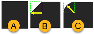
The following list provides guidance for the different stub lead types:
|
Stub Foot Only | |
|
 |
|
Stub Extended Foot | |
|
 |
|
Stub Shoulder Only | |
|
 |
|
Stub Foot & Shoulder | |
|
 |
| Solder Tab |
|
Refer to the section Die Properties Guide.