The Reaction Workbench Mechanism Reduction facility allows you to explicitly control the relative error of simulation targets during the reduction process, such that the reduction is performed iteratively to provide the smallest mechanism possible to achieve the allowed error.
This automated iterative procedure is applied to the Principal Component Analysis (PCA), Directed Relation Graph (DRG), Directed Relation Graph with Error Propagation (DRGEP), Directed Relation Graph with Path Flux Analysis (DRGPFA), the Sensitivity Analysis Option for DRG/DRGEP/DRGPFA, QSSA, and Isomer Lumping methods. With this iterative operation, the user can specify error tolerances on one or more targeted outputs from an Ansys Chemkin simulation, such as flame-speed, ignition-delay time, or NOx prediction. The Reaction Workbench reduction process adjusts the controlling parameter(s) for the reduction method until it achieves the minimum-size mechanism that meets all the user-specified error-control criteria. "Error" is always defined relative to a simulation performed with the unreduced full mechanism, defined through specification in the Target project. In this way, the reduction is independent of the process for validating and improving the full mechanism(s).
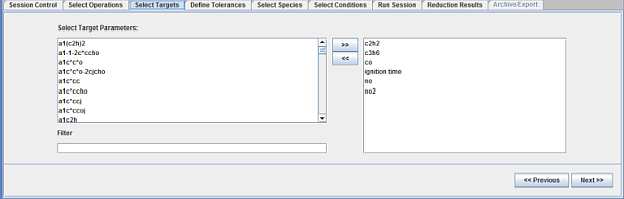
Figure 2.19: Select targets for mechanism reduction operation and Figure 2.21: Monitor the progress of the mechanism reduction operation illustrate the implementation of this iterative operation. Through the separate Reaction Workbench interface, you can either start with an existing Ansys Chemkin project or set up a new project by launching the Chemkin simulation package from within Reaction Workbench. Once the project is ready for use, you will be able to select targeted output variables from a list of simulation outputs available for the particular reactor model(s), as shown in Figure 2.19: Select targets for mechanism reduction operation. This list includes not only the intrinsic solution variables from each reactor model, but also derived variables such as flame-speed, ignition-delay data, heat-release data, and emission indices.
Note: To prevent minor pre-ignition events from being used as targets when selecting ignition delay time (or crank angle) targets for mechanism-reduction operations in Reaction Workbench, select the User Preference option to indicate that only the last ignition time should be used for such targets. This assures that the ignition-delay assessment between the full and reduced mechanism only compares the last (main) ignition event in determining if results are within desired error tolerances.
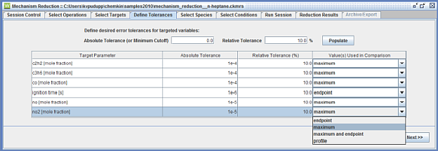
You can then assign error tolerances to individual targeted output, as shown in Figure 2.20: Assign error tolerances to targeted outputs . Often the absolute tolerance can be set to zero, which indicates that all values in the Ansys Chemkin solution for this variable should be considered. However for species fractions, such as PPM of NOx, it may be appropriate to set an absolute tolerance at ~1 PPM (or 1.E-6 mole fraction), for example, to indicate that below that value, it is not important that the mechanism resolve the values accurately. The relative tolerance is set as a percentage of the value as predicted by the full mechanism for the selected Chemkin project. For example, if CA at 10% of heat-release is set as a target and the full mechanism predicts a CA10 value of ~7 CA degrees ATDC, a relative tolerance of 20% would mean that we reduce the mechanism until the CA10 is within 1.4 degrees of that predicted with the full mechanism. In addition, to assign error tolerances, you can also choose to use the entire time/spatial profile of the targeted output parameter or only the end-point value or the maximum value in the solution, as shown in Figure 2.20: Assign error tolerances to targeted outputs . For single-point values such as ignition-delay time or flame speed, if continuations are used in the Reaction Workbench project, this end-point option will employ only the value from the last continuation instead of using values from every continuation.
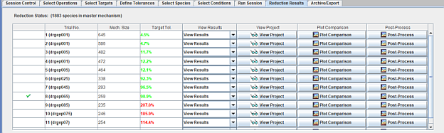
The next Select Species tab provides an opportunity to indicate a subset of species that should be kept in the skeletal mechanism, regardless of the results of the mechanism reduction method. By default, inlet species and major products of combustion will always be included. In addition, if the selected Ansys Chemkin project contains a parameter study that represents a wide range of targeted conditions, the Select Conditions tab allows selection of a subset of those conditions for the reduction operation, if desired. Progress for the mechanism reduction operation is monitored through the Workbench interface, as shown in Figure 2.21: Monitor the progress of the mechanism reduction operation , with a measure of the success of meeting the mechanism-reduction criteria indicated at each iteration. The mechanism reduction operation is driven by the normalized maximum error (difference) between the targeted outputs obtained from the skeletal mechanism and those obtained from the full mechanism. The normalized error is defined as:
 | (2–1) |
where  is the relative tolerance and
  is absolute tolerance.
If the normalized maximum error is less than 1.0, all the tolerance settings of the targeted outputs are satisfied. As more species are removed from the full mechanism, the value of the maximum error will increase. The Workbench operation will track the maximum error throughout the reduction process and stop the reduction when no more species can be removed from the full mechanism while keeping the maximum error less than 1.0. You can interrupt the reduction process at any time and the partial reduction results can be re-used when applicable.