By running Polyflow in Workbench, you can more quickly and efficiently convert your Polyflow output files into other file types. By transferring results between Polyflow-based systems and using the Select results in the following lists dialog box, the conversion of files can be performed without requiring the solver to calculate the full simulation. The following examples demonstrate how to convert a results file into a particular kind of postprocessing file, and how to convert CSV files into a results file.
Consider a situation in which you have run a simulation, but did not set up the data file to generate output files for an external postprocessor, such as FIELDVIEW. If you then decide that you would like to view the results in FIELDVIEW, you can convert a results file from the simulation in the following way:
Create a new Polyflow-based component system next to the system of the completed simulation.
Transfer the mesh to the new system: if the mesh did not change in the original simulation, connect the old Mesh cell to the new Setup cell; otherwise, perform steps 3.(a)–(e) in Stopping, Restarting, and Continuing a Calculation.
Transfer the old results file to the new system:
Create a transfer solution data connection from the old Solution cell to the new Solution cell (as described in Connecting Systems in Workbench).
Right-click the new Solution cell, move your mouse over Preferences..., and select Results Transfer.
In the Select results in the following lists dialog box that opens, make sure that Restart with a single Polyflow results file is selected from the Import option drop-down list.
Select the results file that you want to convert from the Select results file drop-down list. For example: if it was a steady solution, select Last results; if it was a transient solution, you can select any results file of interest, as long as it is compatible with the transferred mesh.
Click in the Select results in the following lists dialog box.
Set up a data file for the new system to convert the old results file.
Double-click the Setup cell to open Polydata.
Click Convert old result files in the main Polydata menu.
 Convert old result files
The Convert old result files menu will open. Note that the top of the menu reports that the mesh and result files generated by the old system are selected for conversion.
If it is a 2D simulation, click Modify type of simulation.
Modify type of simulation
The Type of simulation menu will open. Click the menu item that accurately conveys the kind of simulation you are performing and then click Accept the current setup.
Click Select outputs.
Select outputs
The Outputs menu will open.
Click the menu item for the output file you would like to generate, such as Enable FieldView UNS output.
Enable FieldView UNS output
Click Upper level menu to return to the previous menu.
Click Save and Exit, and then Accept and Continue in the menus that open.
Update the Solution cell of the new system. When the simulation is complete, the output files can be found in the
Outputssubfolder.
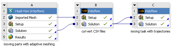
Consider a case where you want to run a simulation that involves moving parts with adaptive meshing (for example, a batch mixer that has a transient flow and utilizes the mesh superposition technique), and you would like to perform particle tracking so that you can then conduct a statistical analysis. Unfortunately, it is not possible in Polyflow to perform particle tracking when the flow domain changes. To resolve this problem, you can convert the CSV files into a set of results files, and then use the results files to compute a set of trajectories for your statistical analysis, as described in the following steps:
Run the moving part simulation with adaptive meshing using Polyflow in Workbench, generating mesh and CSV files for each time step.
Create a new Polyflow-based component system in the Project Schematic.
Connect the Mesh cell from the first system to the Setup cell in the second system (as described in Connecting Systems in Workbench).
Transfer the CSV files generated by the first system to the second system:
Create a transfer solution data connection from the first Solution cell to the second Solution cell (as described in Connecting Systems in Workbench).
Right-click the second Solution cell, move your mouse over Preferences..., and select Results Transfer.
In the Select results in the following lists dialog box that opens, select Restart with a list of Polyflow CSV files from the Import option drop-down list.
Select one of the CSV files generated by the first simulation from the Select results file drop-down list. Note that the prefix of this CSV file will be used by Polydata to identify all of the other related CSV files, so that the entire set is converted.
Click in the Select results in the following lists dialog box.
Set up the data file for the second system using Polydata.
Select the Convert old csv files menu item from the main Polydata menu:
Convert old csv files
Then use the menu items in the Convert old csv files menu to define whether you want to convert a single or multiple CSV files from the first simulation; if you are converting multiple files, indicate the starting and ending indices of the files to convert.
You have the option of setting up the data file to refine the mesh uniformly, by defining the level of refinement and the domain.
Specify that you want Polyflow output produced by clicking Outputs in the main Polydata menu.
Outputs
Then click Enable Polyflow output in the menu that opens.
Enable Polyflow output
You may then use this menu to enable other desired postprocessor output types.
Click Save and exit in the main Polydata menu.
Save and exit
Update the Solution cell of the second system, thus creating a unique mesh and set of results files.
Create yet another Polyflow-based component system in the Project Schematic.
Transfer the mesh created by the second system to the third system:
Create a transfer connection from the second Solution cell to the third Setup cell (as described in Connecting Systems in Workbench).
Right-click the third Setup cell, move your mouse over Preferences..., and select Mesh Transfer.
In the Select a mesh in the following list dialog box that opens, make sure that Select a Polyflow mesh file is selected from the Import option drop-down list.
Select the mesh generated by the second simulation by selecting Mesh (refinement step) [formatted] from the Select mesh drop-down list.
Click in the Select a mesh in the following list dialog box.
Transfer the results files generated by the second system to the third system:
Create a transfer solution data connection from the second Solution cell to the third Solution cell.
Right-click the third Solution cell, move your mouse over Preferences..., and select Results Transfer.
In the Select results in the following lists dialog box that opens, select Restart with a list of Polyflow results files from the Import option drop-down list.
Select one of the results files generated by the second simulation by selecting Result(conv. step <#>)[formatted] from the Select results file drop-down list, where <#> is the ID of the conversion step. Note that the prefix of this results file will be used by Polydata to identify all of the other related results files, so that the entire set is loaded.
Click in the Select results in the following lists dialog box.
Set up the data file for the third system using Polydata, such that mixing task computes a set of trajectories.
Update the Solution cell of the third system.
Launch Polystat by right-clicking the third Solution cell and selecting Polystat, and run a statistical analysis of the mixing based on the trajectories.