


The motion of the moving parts can be both transient and complex. Any type of complex motion can be specified using a user-defined function. Using the specified translational and angular velocities, Ansys Polyflow integrates the translational and angular positions with an implicit Euler scheme. At each time step, the new position is computed by a displacement (translation and rotation) of the moving part in its reference configuration.
The motion is based on the reference position of the moving part, which is the
initial position in the original mesh file. A reference frame ( ) is associated with the reference position, and the rotation
motion is defined. The orientation of the axis of rotation can be changed by
specification of a rotation around the
) is associated with the reference position, and the rotation
motion is defined. The orientation of the axis of rotation can be changed by
specification of a rotation around the  axis, followed by another rotation around the new
 axis. Then a translation can be applied.
The motion is defined in three steps:
Define the rotation in the reference configuration (Figure 22.3: Description of Rotational Motion in the Reference Configuration):
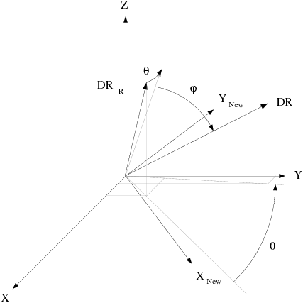
Define the change in direction of the axis of rotation,
 by a rotation of angle
  around the
  axis, followed by a rotation of angle
  around the new
  axis (Figure 22.4: Description of the Change of Orientation of the Rotation
Axis):
axis (Figure 22.4: Description of the Change of Orientation of the Rotation
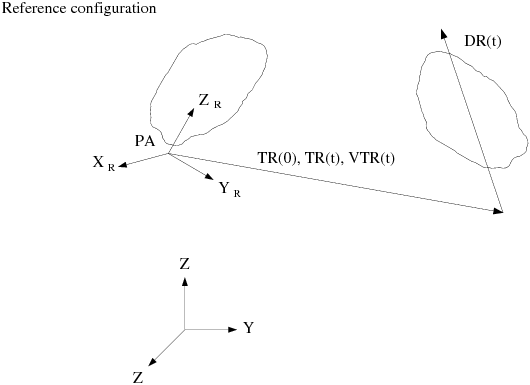
Axis): Define the translation (Figure 22.5: Description of Translation):


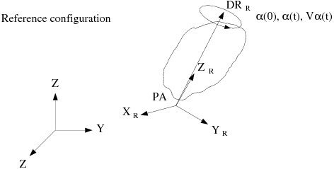


The following quantities are specified by you during the problem setup in Ansys Polydata:
Direction of the rotation axis in the reference configuration,

Point of the rotation axis, PA
Angular velocity,
 , in RPM
 Initial rotation angle,
 , in degrees
 Angles
 and
and  , in degrees
 Angular velocities
 and
and  , in RPM
 Initial translation,

Translation velocity,

The positions (translation  and rotation angles
  ,
,  , and
, and  ) are integrated by an implicit Euler scheme:
 | (22–10) |
This integration produces a vector of translation and a matrix of rotation. In
order to guarantee the accuracy of the Euler scheme, each time step is divided
into substeps of size on the order of  . The maximum number of substeps is 10,000. At each time step,
the new position of the moving part is obtained by applying a translation
followed by a rotation of the reference position. This technique avoids error
accumulation that can lead to deformation of the moving part. Note that the
substeps are used only to integrate the position (translation, angles of
rotation), while the position itself is computed only once per time step.
. The maximum number of substeps is 10,000. At each time step,
the new position of the moving part is obtained by applying a translation
followed by a rotation of the reference position. This technique avoids error
accumulation that can lead to deformation of the moving part. Note that the
substeps are used only to integrate the position (translation, angles of
rotation), while the position itself is computed only once per time step.
In order to compute the new position, the translation vector and matrix of
rotation are needed. In the reference configuration, the reference frame
( ) is defined such that the
  axis is aligned with the direction of the rotation axis
 . The transformation matrix from (
 ) to (
 ) is denoted by
  in the following relation:
 | (22–11) |
 is composed of two rotations: the first around the
 axis with an angle of
  , and the second around the
  axis with an angle of
  . Figure 22.6: Transformation Between the (X, Y, Z) and (XR,
YR, ZR) Frames shows the reference frames and how the rotations are defined.
. Figure 22.6: Transformation Between the (X, Y, Z) and (XR,
YR, ZR) Frames shows the reference frames and how the rotations are defined.
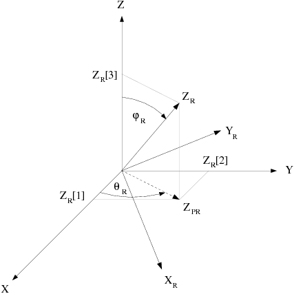
The transformation matrix for the first rotation is given by
 | (22–12) |
and the transformation matrix for the second rotation is given by
 | (22–13) |
Thus, the transformation matrix for the combination of both rotations is given by
 | (22–14) |
In Equation 22–12, Equation 22–13, and Equation 22–14, the cosine and sine of the angles are given by
 | (22–15) |
By definition,  is always positive.
 in Figure 22.6: Transformation Between the (X, Y, Z) and (XR,
YR, ZR) Frames is the projection of
in Figure 22.6: Transformation Between the (X, Y, Z) and (XR,
YR, ZR) Frames is the projection of  onto the plane
  . If this projection is a point, it is assumed that
 .
.
Similarly, the transformation matrix  to align the reference axis of rotation
  with the current direction of the rotation axis
 is given by
 | (22–16) |
The matrix of rotation in the reference frame is denoted by  and is given by
 | (22–17) |
To obtain the current position of a point P with the coordinates
 , the following transformations are applied:
Translate
 to move the point in the reference frame:
(22–18)
Change the frame from (
 ) to (
 ):
): 
(22–19)
Apply the rotation angle
 in the reference frame:
(22–20)
Change the frame from (
 ) to (
 ):
): 
(22–21)
Rotate around the
 axis by
  , and around the new
  axis by
  :
: 
(22–22)
Translate PA:

(22–23)
Take into account the translation
 :
: 
(22–24)


