


The Graphical window menu allows you to modify the parameters of the Graphics Display window.
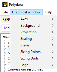
- Axes
allows you to display/erase the axes of the coordinates system.
- Background
modifies the background color.
- Projection
offers the choice between Perspective and Orthographic projections.
- Scaling
allows non-isotropic zooming.
- Views
changes the view to the plane perpendicular to the axis you select from a positive coordinate on that axis; repeatedly selecting an axis will cause the view to alternate with the view from a negative coordinate.
- Sizing Points
allows you to increase/decrease the size of points appearing in the Graphics Display window. Such points are displayed when defining a Probe in the Outputs menu (see Saving Data at a Specified Point for more information) or a transformation method in a mesh deformation preprocessor (see Die Shape Parameterization for more information). As the default size of those points is automatically set according to the dimensions of the geometry, this feature is sometimes useful to change their size in the Graphics Display window.
- Sizing Darts
allows you to increase or decrease the size of darts in the Graphics Display window. The darts are displayed automatically when required by the setup, such as when you click Specify mold side / cavity side in the Modification of a contact problem menu when setting up a contact detection problem for a shell task, or when you define the settings in the Diffuse gray wall parameters menu for an internal radiation problem. The size of the dart is initially based on the dimensions of the geometry.
- Logo
provides options related to the Ansys logo displayed in the Graphics Display window. You can change the color of the logo to black or white, and you can specify if you want to show or hide it.