


In the rubber manufacturing industry, products may consist of reinforced compounds, that is, a material in which a reinforcing media (for example, fibers) are embedded in a matrix. Fibers are often oriented along a given direction, and hence confer an orthotropic property to the compound. In simple terms, they restrain or hinder the deformation of the compound along the direction of orthotropy. From this simple consideration, it is quite natural to consider a constitutive model that consists of two parts: a part for the unreinforced rubber matrix, and a part for the reinforcement structure.
Consider a reinforced incompressible material. In general, it would be easier to write the constitutive equation in a reference frame locally aligned with the main direction of the reinforcement fibers. However, geometric or process considerations often suggest using a Cartesian reference frame that is not necessarily aligned with the main direction of orthotropy. In this selected reference frame, the orthotropy is defined using direction cosines.
In the selected Cartesian reference frame, the constitutive equation can be written as follows:
 | (10–25) |
where  and
and  are the total stress tensor and the rate-of-deformation tensor,
respectively, written in the selected reference frame, while
are the total stress tensor and the rate-of-deformation tensor,
respectively, written in the selected reference frame, while  is the pressure and
  is the unit tensor. Two terms involve the rate-of-deformation
tensor: they are the contribution from the matrix and the contribution of the
reinforcement fibers. As can be seen, both contributions are described by means of
fluid models. The quantity
is the unit tensor. Two terms involve the rate-of-deformation
tensor: they are the contribution from the matrix and the contribution of the
reinforcement fibers. As can be seen, both contributions are described by means of
fluid models. The quantity  is the shear viscosity of the unreinforced matrix, and can be
described by one of the models described previously in Shear-Rate-Dependent Viscosity Laws.
is the shear viscosity of the unreinforced matrix, and can be
described by one of the models described previously in Shear-Rate-Dependent Viscosity Laws.
In Equation 10–25,  is the fourth-order orthotropic property tensor given in the
selected reference frame. Formally, for an orthotropic material, the quantity
is the fourth-order orthotropic property tensor given in the
selected reference frame. Formally, for an orthotropic material, the quantity
 has ten parameters. In view of the decomposition suggested in
Equation 10–25, it is possible to build
has ten parameters. In view of the decomposition suggested in
Equation 10–25, it is possible to build  on the basis of the components of the local direction of
reinforcement fibers (which coincide with the direction cosines of the anisotropy)
and a constant (high) viscosity that acts as the reinforcement magnitude. Typically,
this reinforcement magnitude can be 100 times higher than the viscosity of the
unreinforced matrix; and is assumed to be constant throughout a calculation.
on the basis of the components of the local direction of
reinforcement fibers (which coincide with the direction cosines of the anisotropy)
and a constant (high) viscosity that acts as the reinforcement magnitude. Typically,
this reinforcement magnitude can be 100 times higher than the viscosity of the
unreinforced matrix; and is assumed to be constant throughout a calculation.
At the beginning of a shaping process, most reinforced parts are often planar or cylindrical. In general, the direction of reinforcement fibers is assumed to be uniform at the beginning of a forming process and can involve up to three individual massless reinforcements. When the deformation of the matrix remains moderate, it is assumed that the direction of reinforcement is unaffected and it will not be updated. However, in situations involving large deformations of the matrix, the direction of reinforcement may change with time and become non-uniform (assuming that the reinforcements are not too stiff).When this happens, you should click Enable update of reinforcements orientation.
Reinforcement cords can be defined for 3D models as well as for shell models. For both 3D and shell models, the same data need to be specified, i.e. a reinforcement orientation and a reinforcement magnitude.
For 3D models, there are no specific limitations for the initial geometric configuration. For shell models, the recommended initial configuration should be a flat sheet or a cylindrical sheet whose symmetry axis coincides with one of the Cartesian axes. This is needed for an easy specification of the initial orientation of the reinforcements. Indeed, the initialization of the reinforcement sets is limited to Cartesian and cylindrical descriptions. The latter one is useful for 3D cylindrical objects.
For specifying a Cartesian orientation of the reinforcement set, the direction cosines of the reinforcements must be entered. For specifying a cylindrical distribution of the orientation of the reinforcement set, it is at first important to make sure that the axis of the cylinder is one of the Cartesian reference frame. We then apply the following scenario:
The axis of the cylinder must be one of the Cartesian axis x (resp. y or z);
In the y direction (resp. z or x), a zx plane (resp. xy, or yz) is defined tangent to the cylinder;
The local orientation angle of the reinforcement is defined in that plane with respect to the axes defining that plane, and that very angle is used all around the cylinder
This scenario is illustrated in the figure Figure 10.2: Cylinder Orientation for cylinders whose axis is successively along the x-, y- and z-direction.
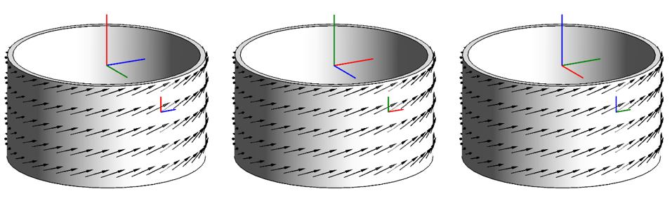
Figure 10.2: Cylinder Orientation shows three scenarios with the axis of the cylinder being successively the x-, y- and z-axis, respectively displayed with the usual color convention (red=x, green=y, blue=z). (Left): With the x-axis being the axis of the cylinder, the angle is measured with respect to the z-direction in a zx-plane tangent to the cylinder. (Middle): With the y-axis being the axis of the cylinder, the angle is measured with respect to the x-direction in a xy-plane tangent to the cylinder. (Right): With the z-axis being the axis of the cylinder, the angle is measured with respect to the y-direction in a yz-plane tangent to the cylinder.
Note: When planes of symmetry are used in the model, they should preferably be perpendicular to the orientation of the reinforcement so that the reinforcement will not exhibit any virtual kink at the symmetry plane.
When setting up the simulation case for shell models, the orientation of reinforcement should preferably be parallel to the sheet in the initial configuration, as any component transverse to the plane of the polymer sheet will be discarded.
Eventually, shell models usually involve large deformations, so that the orientation of reinforcements will be automatically updated by the solver.