The procedure for setting up an elastic problem for a solid region coupled with a flow problem, is described below. This process assumes that you know how to define a flow problem in Ansys Polyflow.
Create a sub-task for the elastic problem.
 Create a sub-task
Select the appropriate problem type from the Create a sub-task menu.
For an isothermal elastic problem in a solid region coupled with flow problem, select:
 Elasticity (isothermal)
For a nonisothermal elastic problem in a solid region coupled with flow problem, select:
 Elasticity (non-isothermal)
For an isothermal elastic postprocessing in a solid region, select:
 Postprocessor Elasticity (isothermal)
For a nonisothermal elastic postprocessing in a solid region, select:
 Postprocessor Elasticity (non-isothermal)
When prompted, enter a name for the sub-task.
Specify the region where the elastic sub-task is to be applied.
 Domain of the sub-task
Define the material properties.
 Material data
Define the elastic data.
 Elastic data
For an elastic problem, enter values for the Young’s Modulus (
) and the Poisson’s ratio (
), as defined in Equation 27–2.
 Modify E
 Modify Mu
Important: Note that while Poisson’s ratio is referred to as Mu in the previous menu item, it is elsewhere denoted by
(for example, Equation 27–2).
By default the effect of an elastic deformation on the flow domain is active. Select Switch to [no update of coordinates] to ignore this effect.
 Switch to [no update of coordinates]
For a nonisothermal elastic problem, specify the lineic dilatation coefficient (
) and the reference temperature for dilatation (T
), as defined in Equation 27–2.
 Modify B0
 Modify Tref
Specify the temperature dependencies of the Young’s Modulus, the Poisson’s ratio and the lineic dilatation coefficient. Note that the default setting is no temperature dependence.
 + temperature dependence on E
 + temperature dependence on Mu
 + temperature dependence on B
Select Modify temperature dependence law,
 Modify temperature dependence law
and choose from the following:
 Switch to [no temperature dependence] law
 Switch to [Arrhenius approximate] law
 Switch to [Arrhenius] law
For transient cases, specify the density (
) and whether the acceleration terms are taken into account in Equation 27–1.
 Density
 Inertia terms
For non-isothermal cases, specify heat conduction parameters: thermal conductivity (
) (Equation 13–2), density (
), specific heat capacity (C
), and heat source per unit volume (
) (Equation 13–5).
 Density
 Thermal conductivity
 Heat capacity per unit mass
 Heat source per unit volume
For non-isothermal cases, specify also an average temperature, which is used as an initialization value for facilitating convergence of non-linear steady (or evolution) cases and as an initial temperature for transient cases.
 Average temperature
For a nonisothermal elastic problem, define the thermal boundary conditions.
 Thermal boundary conditions
Follow the procedure for the heat conduction problem in Problem Setup.
Define the displacement boundary conditions.
 Displacement boundary conditions
Select the boundary you want to set the displacement conditions for.
Click Modify.
Select the boundary condition type you want to impose. By default, Ansys Polydata imposes zero displacement for each external boundary.
Choose Interface with a solid to specify an interface between 2 elastic solids.
 Interface with a solid
Choose Interface with a fluid to specify an interface between an elastic solid and a flow domain.
 Interface with a fluid
Choose Normal and tangential displacement imposed (dn, ds) to specify the normal and tangential displacement on the boundary.
 Normal and tangential displacement imposed (dn,
ds)
For each component, select the appropriate specification method:
 Constant to impose a constant value
for the current component of the displacement.
  Linear function of coordinates to
impose a linear function of the form d=A+Bx+Cy+Dz for
the current component of the displacement.
  Map from CSV (Excel) file to impose
a displacement profile contained in a CSV file for the
current component of the displacement.
  User-defined function to impose a
displacement profile using a user-defined function for
the current component of the displacement.
Choose Normal and tangential force imposed (fn, fs) to specify the normal and tangential forces, respectively, along the boundary.
 Normal and tangential force imposed (fn,
fs)
For each component, select the appropriate specification method:
 Constant to impose a constant value
for the current component of the force.
  Linear function of coordinates to
impose a linear function of the form d=A+Bx+Cy+Dz for
the current component of the force.
Choose Normal displacement and tangential force imposed (dn, fs) to specify the normal displacement and zero tangential force, respectively, on the boundary.
 Normal displacement and tangential force imposed (dn,
fs)
For the normal displacement, select the appropriate specification method:
 Constant to impose a constant value
for the normal displacement.
  Linear function of coordinates to
impose a linear function of the form d=A+Bx+Cy+Dz for
the normal displacement.
  Map from CSV (Excel) file to impose
a displacement profile contained in a CSV file for the
normal displacement.
  User-defined function to impose a
displacement profile using a user-defined function for
the normal displacement.
Choose Normal force and tangential displacement imposed (fn, ds) to specify the normal force and zero tangential displacement, respectively, on the boundary.
 Normal force and tangential displacement imposed (fn,
ds)
For the normal force, select the appropriate specification method:
 Constant to impose a constant value
for the normal force.
  Linear function of coordinates to
impose a linear function of the form d=A+Bx+Cy+Dz for
the normal force.
Choose Plane of symmetry (fs =0, dn =0) to specify the symmetry condition. No further inputs are required.
 Plane of symmetry (fs=0,dn=0)
Choose Contact with a parison to apply the contact force from the parison on the contact surface of a mold. Note that this option is available only for an elastic postprocessor.
 Contact with a parison
Choose Border of a moving part to apply the contact force from the fluid on border of a moving part. Note that this option is available only for an elastic postprocessor.
 Border of a moving part
Choose Assign displacement at points to impose a displacement at designated points, in the computational domain.
 Assign displacement at points
Create a new constraint.
 Creation of a new constraint
Enter a name of the constraint, and specify the position by selecting Modify coordinates of points.
 Modify coordinates of points
Specify which component you want to impose (-X, -Y or -Z).
 Impose displacement-X
Specify the value of the displacement component (-X, -Y or -Z).
 Modify displacement-X
Modify the interpolation scheme (optional).
 Interpolation
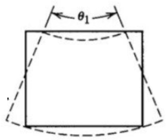
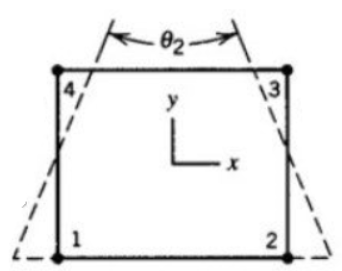
The default interpolation for the displacement is linear. The linear interpolation is inexpensive and leads to good results unless the deformation is mainly bending.
In the case of a pure bending, there is no shear strain but if a linear interpolation is used to represent the deformation, a spurious shear strain is introduced. A shear strain that corresponds to a strain energy that makes the material apparently very stiff to bending.
It is thus recommended to switch to quadratic interpolation of the displacement when bending is significant in the deformation.
 Quadratic displacement
It would be cautious to switch to quadratic interpolation when you are unsure of the importance of bending.
Note: Quadratic interpolation of coordinates is not mandatory when using quadratic interpolation of displacement, however, if quadratic interpolation of coordinates is used, then the quadratic interpolation of displacement is mandatory. See Selecting an Interpolation for more information on interpolation.
Create a sub-task for the flow problem.
 Create a sub-task
Define your flow sub-task (for example, domain, material data...). Note that Ansys Polydata detects interfaces with fluid boundary conditions for which a flow problem has yet to be defined and prompts you to define a flow sub-task.
Define the flow boundary conditions (for example, inflow, wall, outflow) for all boundary conditions except between the flow and solid domains.
 Flow boundary conditions
Select the boundary you want to set the interface with solid condition for and click Modify.
Select the Interface with elastic solid condition.
 Interface with elastic solid
If you want to apply a slip boundary condition, click Switch to slip condition. Otherwise, a stick condition (zero velocity) is applied by default.
 Switch to slip condition
If you applied a slip boundary condition, specify the slipping and penalty coefficient.
 Modify Fslip
 Modify penalty coef.
If you applied a stick boundary condition, specify the stability coefficient. The FSI formulation uses this stability coefficient to help resolve problems that arise from conflicting boundary conditions. Note that this stability coefficient is effective only when a continuous interpolation is selected (see the step that follows).
 Modify stability coef.
For either slip or stick boundary conditions, you can modify the interpolation rule.
 Modify interpolation rule
In most cases, the default selection (constant per element) is suitable. When your calculation fails due to FSI, it is recommended that you try the interpolation that is the same as that used for the velocity field or the pressure field. In any case, it is recommended that you carefully inspect the results upon completion of the calculation.
If you have selected the update of coordinates option for a material parameter of the elastic sub-task, you must specify the global remeshing of the flow domain.
 Global remeshing
Define the elastic remeshing that is required, paying particular attention to the compatibility between boundary conditions of the remeshing and boundary conditions of the elastic sub-task.


