For 2D axisymmetric extrusion simulations, you can compute the parison thickness. The parison being extruded has at least two surfaces. At each point in the domain, Ansys Polyflow computes the distance between the point and both the inner and the outer surfaces. A symmetric calculation is performed, and at a given location or height along the surface, a unique quantity is given. This method can be used to compute the thickness of a parison being extruded, or the thickness of a blown product.
Important: The calculation method is valid for relatively thin objects, with little variation in thickness; it is not appropriate for thick objects.
The procedure for setting up the calculation of the parison thickness is as follows:
Create a new sub-task.
 Create a sub-task
Select Postprocessor as the sub-task type. When prompted, enter a name.
Postprocessor
In the F.E.M. Task Postprocessor menu, select Parison thickness.
Parison thickness
By default, parison #01 is already created. To create a new one, select Creation of a new parison. To delete a parison, select Deletion of a parison.
Select the parison for which you want to compute the thickness (for example, parison #01).
parison #01
Specify the region where the postprocessor sub-task applies.
Domain of the sub-task
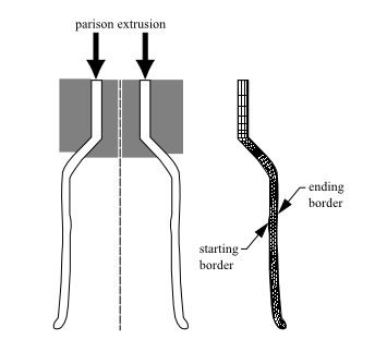
Specify the boundary sets representing the starting and ending borders to be used in the thickness calculation (see Figure 30.3: Starting and Ending Borders for Parison Thickness Calculation).
Ansys Polyflow will evaluate the distance between these borders at a point within them to determine the thickness at that location.
Borders for thickness calculation
In the resulting Borders for thickness calculation panel, select the boundary set representing the first border (or a portion of it) and click Modify.
Choose Starting border.
Repeat the previous two steps if other boundary sets are needed to completely define the starting border.
Select the boundary set representing the second border (or a portion of it) and click Modify.
Choose Ending border.
Repeat the previous two steps if other boundary sets are needed to completely define the ending border.