


optiSLang supports the definition of a text based project format (*.opx).
Basic Structure
optiSLang OPX requires four basic entries:
INFO: Contains the optiSLang version.
NODES: Contains the project structure with node hierarchy and node names.
EDGES: Contains the connections between nodes.
NODE_ATTRIBUTES: Describes types, settings and properties of nodes.
Example:
<?xml version="1.0" ?>
                <OPX>
                    <INFO>
			<VERSION>700</VERSION>
                    </INFO>
                    <NODES></NODES>
                    <EDGES></EDGES>
                    <NODE_ATTRIBUTES></NODE_ATTRIBUTES>
                </OPX>
NODES
The NODES section contains the project structure and can represent a nested hierarchy of systems and nodes. At least one basic NODE entry for the scenery (ROOT) is required.
Each NODE entry requires an ID attribute containing the node name (not the node type).
Example:
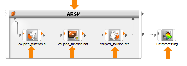
                <NODES>
                    <NODE ID="ROOT">
                        <NODE ID="ARSM">
                            <NODE ID="coupled_function.s">
                            <NODE ID="coupled_function.bat">
                            <NODE ID="coupled_solution.txt">
                        </NODE>
                        <NODE ID="Postprocessing">
                    </NODE>
                </NODES>
EDGES
Edges represent the connections between the nodes. Each EDGE entry requires the following attributes:
FROM: ID of the sending node.
FROMSLOT: Name of the output slot.
TO: ID of the receiving node.
TOSLOT: Name of the input slot.
Example:
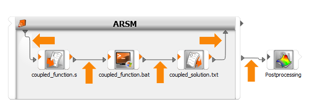
                <EDGES>
                    <EDGE FROM="ARSM" FROMSLOT="IODesign" TO="coupled_function.s" TOSLOT="IDesign"/>
                    <EDGE FROM="coupled_function.s" FROMSLOT="ODesign" TO="coupled_function.bat" TOSLOT="IDesign"/>
                    <EDGE FROM="coupled_function.bat" FROMSLOT="ODesign" TO="coupled_solution.txt" TOSLOT="IDesign"/>
                    <EDGE FROM="coupled_solution.txt" FROMSLOT="ODesign" TO="ARSM" TOSLOT="IIDesign"/>
                    <EDGE FROM="ARSM" FROMSLOT="OMDBPath" TO="Postprocessing" TOSLOT="IMDBPath"/>
                </EDGES>
NODE_ATTRIBUTES
For each NODE in NODES, an ATTRIBUTES section with at least the following entries is required:
ID: Node ID (same as in the NODES section).
TYPE: Node type.
Example:
                <NODE_ATTRIBUTES>
                    <ATTRIBUTES>
                        <ID>ROOT</ID>           <!-- REQUIRED, FIXED -->
                        <TYPE>RootSystem</TYPE> <!-- REQUIRED, FIXED -->
                    </ATTRIBUTES>
                </NODE_ATTRIBUTES>
Parameters
A parametric system should always contain at least one dummy parameter to avoid warnings and error messages.
Example:
  <ATTRIBUTES>
                    <ID>ARSM</ID>
                    <TYPE>ARSMActor</TYPE>
                    <PARAMETERS PARAMETER_MERGING_MODE="PREFER_PROPERTY">
                        <PARAMETER CONSTANT="False" NAME="dummy" TYPE="DETERMINISTIC" VALUE="1.0" VALUETYPE="REAL">
                            <OPTIMIZATIONATTS LOWERBOUND="0.0" OPTIMIZATIONTYPE="CONTINUOUS" UPPERBOUND="2.0"/>
                        </PARAMETER>
                    </PARAMETERS>
                </ATTRIBUTES>
Unsupported Nodes/Modules
The following nodes or modules are unsupported. When a project contains an item from the list, the export to OPX fails.
Abaqus Process
Data Mining
Design Export
LS-DYNA Input
Memetic (Beta)
Monitoring
Octave
Process
Raw data export
Raw data import
Tagged Input
TurboOpt Input