


The explicit closest point projection implements the point-to-plane closest point projection by Hallquist et al. [6].
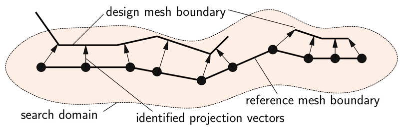
The algorithm first identifies all segments on the design mesh boundary that are in the neighborhood of any node on the reference mesh boundary. On these candidate segments, the point closest to the reference node is determined. If this closest point is inside of a segment, the resulting deviation vector is always perpendicular to the design mesh boundary segment. Otherwise, the projection point is located on a segment’s edge or vertex.
The algorithm only considers segments within a user-specified search distance. If multiple segments are intersected along the given direction, the segment with the shortest distance is chosen. Only segments equally oriented in space are matched. (The dot product of the reference mesh nodal normal vector and the design mesh boundary segment normal vector is positive.)
To simplify the generation of new geometries, the actual deviation vector is defined as the projection of the vector to the closest point (on the matched segment) onto the nodal normal vector of the reference mesh boundary. The normal coordinate deviation is the magnitude of this projected vector. The sign of the normal deviation is positive if the dot product of the deviation vector and the reference mesh’s nodal normal vector is positive.
Features
Requires well defined orientation of shell elements in FEM meshes.
Always detects a projection within the search distance. It can also find projection points in vicinity of holes, cut-offs, and so on.
Search distance influences the numerical efficiency of the search. Ideally, the magnitude of the search distance should be close to the average finite element size.
Note:
To find a projection in a reasonable amount of time, you should try to limit the search distance. When starting with small values, check the maximum deviation that is found. If it is too close to the maximum search distance, increase the distance and repeat the projection.
You should visualize the imported deviations for each design in oSP3D. There, you can see the regions for which no projection could be detected.