


This multi-part tutorial shows how to import field data from Ansys Mechanical:
Note: This tutorial requires installations of both Ansys optiSLang and Ansys Mechanical.
To prepare data for export in Mechanical:
In Ansys Workbench, open the archive file circuit.wbpz in
oSP3D_examples\ansys\circuit.Rename the project to circuit_to_sos and save it as a project file in the same folder.
If you see a message indicating that the oSP3D extension will be upgraded permanently when you save the project, click .
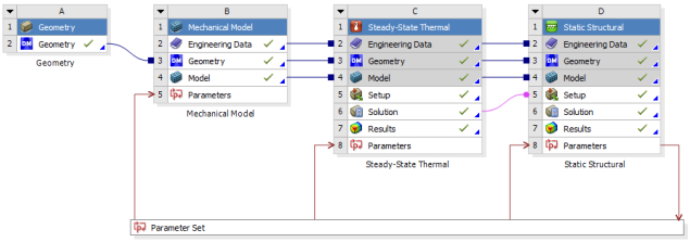
Open the Parameter Set bar and verify the parameters.
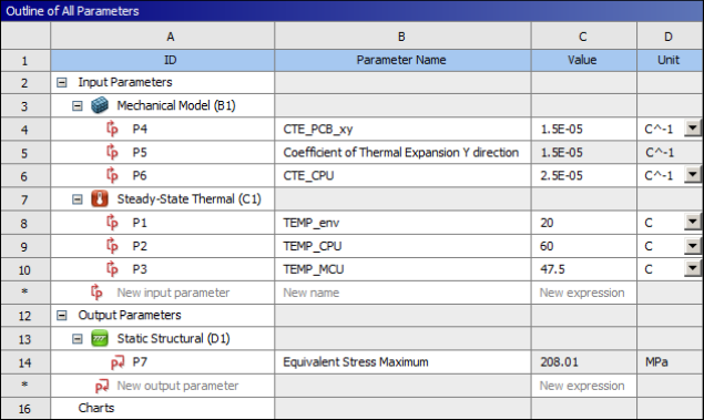
The mechanical simulation has three input parameters.
The thermal simulation has three input parameters.
The static structural simulation has one output parameter: .
Close the Parameter Set bar.
The mechanical simulation has three input parameters.
The thermal simulation has three input parameters.
There is one output parameter: .
You can now complete these preparation procedures:
To prepare the thermal model:
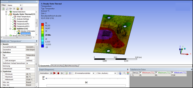
Open the thermal model, solve it, and check the solution.
In the Mechanical ribbon, select >
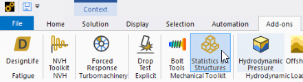
On the oSP3D tab, select > .
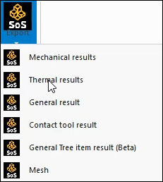
An Export results (SoS) node is added to the Solution block.
Use the box select method to select all bodies in the model view.
Configure the Export results (SoS) node:
Save all 23 bodies for the mesh part.
Export all 23 bodies to oSP3D
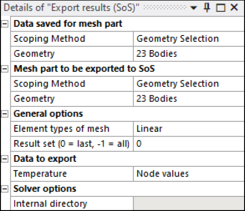
Generate the data of the Export results (SoS) node.
In the Outline view, right-click the Solution node and select Open Solver Files Directory to see the files that have been created.
In the generated SoS_Export folder, verify the export of the mesh and field data:
The file sos_mesh.cdb contains the exported mesh part.
The file sos_results.k is the LS-PrePost output file contains the exported field data. For information on supported LS-PrePost keywords, see LS-PrePost Files in the optiSLang 3D Post-Processing User's Guide.
To prepare the Mechanical model:
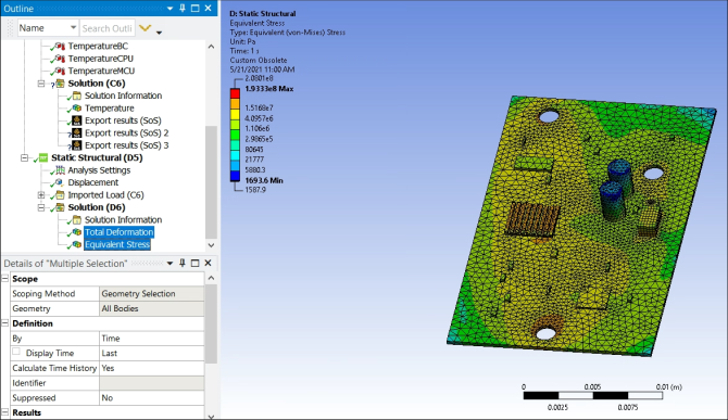
Open the Mechanical model, solve it, and check the solutions for Total Deformation and Equivalent Stress.
In the Mechanical ribbon, select >
On the oSP3D tab, select > .
An Export results SoS) node is added under Solution.
Use the box select method to select all bodies in the model view.
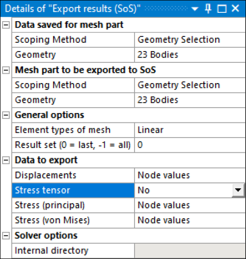
Configure the Export results SoS) node:
Save all 23 bodies for the mesh part.
Export all 23 bodies to oSP3D
Export Displacements, Stress (principal), and Stress (von Mises) as node values.
Save the project and close Workbench.
In the folder for the project:
dp0\SYS-1\MECH\SoS_Export contains the thermal results.
dp0\SYS-2\MECH\SoS_Export contains the mechanical results.
You can now select output files that are saved to optiSLang design directories.
To select output files that are saved to optiSLang design directories:
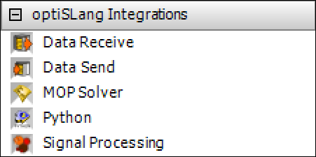
From under optiSLang Integrations in the Workbench Toolbox, insert a Data Send system in the Project Schematic.
Connect the Solution cell in the Static Structural system to the Setup cell in the Data Send system.
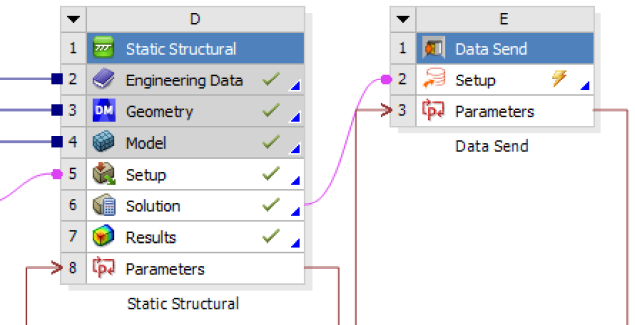
In the Data Send system, double-click the Setup cell.
Select the files sos_mesh.cdb and sos_results.k files for export:
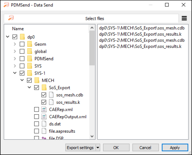
Click .
You can now perform a DOE in optiSLang.
This multi-part tutorial shows how to perform a DOE in optiSLang:
To set up a DOE in optiSLang:
Start a new project in optiSLang and start the Solver wizard.
Under Integrations, select Ansys Workbench.
On the Ansys Workbench connection page, open the Workbench project file circuit_to_sos.wbpj that you saved previously, making sure that the correct Workbench executable is used.
Click .
On the Integrated Solver Settings page:
Drag all inputs to the Parameter list.
Drag the output variable Equivalent Stress Maximum to the Response list.
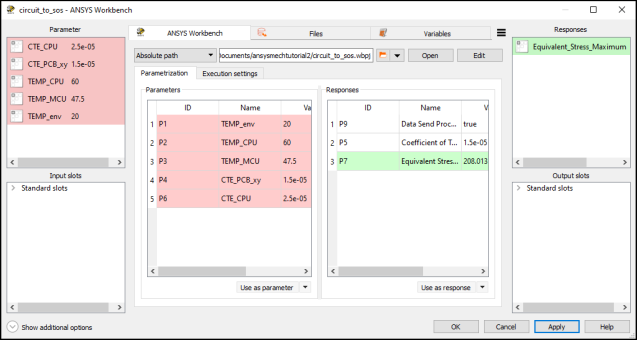
Set the parameter ranges as shown in this image:
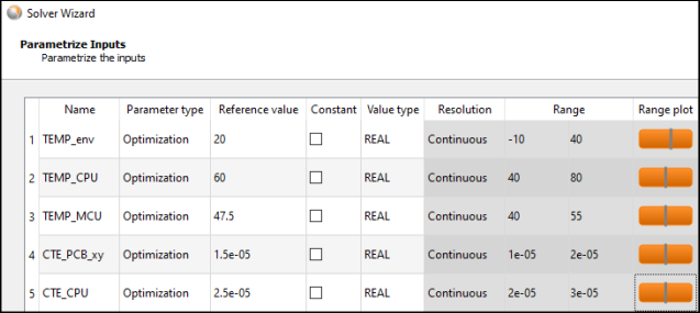
Tip: For quicker entry, you can type the range in the format
min:max-10:40for the first entry.Complete the Solver wizard.
Save and run the optiSLang project.
Drag the Sensitivity wizard onto the solver chain's title bar.
In the Sensitivity wizard, do the following:
Set Sampling method to Advanced Latin Hypercube Sampling.
On the Additional options page, clear the Create MOP check box.
You will create a field-MOP with oSP3D later.
Complete the Sensitivity wizard.
Save and run the optiSLang project.
Running the DOE takes some time. Once the DOE is complete, postprocessing opens so that you can check the results for plausibility.
You are now ready to prepare the DOE data for oSP3D import.
To import DOE data prepared in optiSLang into oSP3D:
Start a new oSP3D project.
Set the file sos_mesh.cdb as the reference mesh:
Select > > .
For the file format, select Ansys Mechanical input files.
Open the file sos_mesh.cdb in the optiSLang project directory (circuit_doe.opd\Sensitivity\Design0001\dp0\SYS-1\MECH\SoS_Export).
Set a named selection:
Select > > .
Set nodes used for statistics/models to SOS_DATA_NODES.
Set elements used for statistics/models to SOS_ELEMENT_NODES.
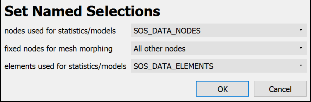
These named selections contain the nodes and elements on the printed circuit board's surface only. Subsequent analysis in oSP3D is performed on these named selections.
Select > > .
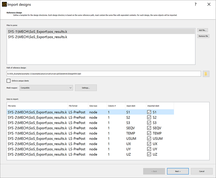
In the Import designs wizard, do the following:
Add the result files of the mechanical and thermal simulation.
Set the file format to LS-PrePost output files:
circuit_doe.opd\Sensitivity\Design0001\dp0\SYS-1\MECH\SoS_Export\sos_results.k
circuit_doe.opd\Sensitivity\Design0001\dp0\SYS-2\MECH\SoS_Export\sos_results.k
Set Path of reference design to circuit_doe.opd\Sensitivity\Design0001.
Select all field data quantities for import and complete the Import designs wizard:
Select > > .
Open circuit_doe.opd\Sensitivity.omdb and import the input parameters.
Verify successful import of all field designs and scalar input parameters.
To support the tutorials in Advanced Field-MOP Tutorials, execute the script for calculating logarithmic equivalent stress and adding it as a new field quantity identifier
LOGSEQV:Copy this script.
local inputs = sos.database():data():filterType(sos.NODE_DATA):filterQuantity("SEQV"):samples():active()  -- get all active designs of SEQV
for i=1,inputs:size() do                                    -- loop over all selected data objects
    local seqv = inputs[i-1]                                -- get the i-th data object
	local design = seqv:ident():design();		    -- get the design ident of the current object
	local seqv_data = seqv:getData();		        -- get the data vector of the current object
	local logseqv_data = seqv_data:CW():Log();	      -- apply the logarithm to all entries in the data vector
	local logseqv = sos.createNodeDataObject(
        		  sos.database(), logseqv_data, true
	);						              -- insert new object into database
	local new_ident = sos.DataObjectKey(design, "LOGSEQV") -- define the ident of the new object
	sos.database():data():insert(new_ident, logseqv)       -- insert new object into database
end
Paste the script into the oSP3D command line as shown.
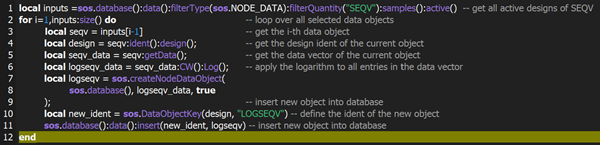
Press the Enter key.
You have finished the DOE data import. You can either move on to the next tutorial or jump to the tutorials in Advanced Field-MOP Tutorials.