When Beta Options are active, you can now create a Gasket Line Pressure result. This result creates line pressure values for a normalized sealing load acting on a gasket, per unit length. This enables you to detect fluid leaks across the area of the gasket. This result maps the forces to an ordered array of points along an imaginary curve at the center line of the gasket. This curve is then presented in graphical and tabular form.
This result requires a corresponding scoping beta feature: a Construction Geometry Path specified as an . This path creates multiple quasi parallel curves that you apply to the gasket surface.
Using the defined offset path, that includes user-defined discretization points as well as sub-paths, you can integrate pressures and determine loading along an imaginary center line of the gasket surface.
Once you evaluate a Gasket Line Pressure result, the application presents the force loads along the center line as well as the pressures detected along each sub-path.
You can use the Chart feature to compare multiple gasket line pressure results.
Define an Offset Path
In order to create an Offset Path, you must have a circular geometry.
Using the Construction Geometry option, , specify the Path Type property as .
Define the geometries of the path:
Under the Reference category of the Details pane, select a desired edge to define the Reference Geometry property.
Under the Offset Guide category of the Details pane, select the interior edge of the body to define the Offset Geometry property.
The application automatically creates sub-paths in between the selected edges using the values of the Discretization Points (the default setting is
47) and Number of Subpaths (the default setting is3) properties. You can change these values as desired.
Define Gasket Line Pressure Result
In order to solve this result, you need to first define loading along the center line of the gasket body. This can be done by creating a beam and scoping the beam to a Bolt Pretension load.
Specify the result:
From the Solution object, open the Gasket drop-down menu and select .
Set the Scoping Method property to .
Set the Path property to the offset path created above. Make sure that the Geometry property displays a single body that contains the offset path.
Verify a meaningful Display Time property setting. It should not be set to zero.
Solve the analysis.
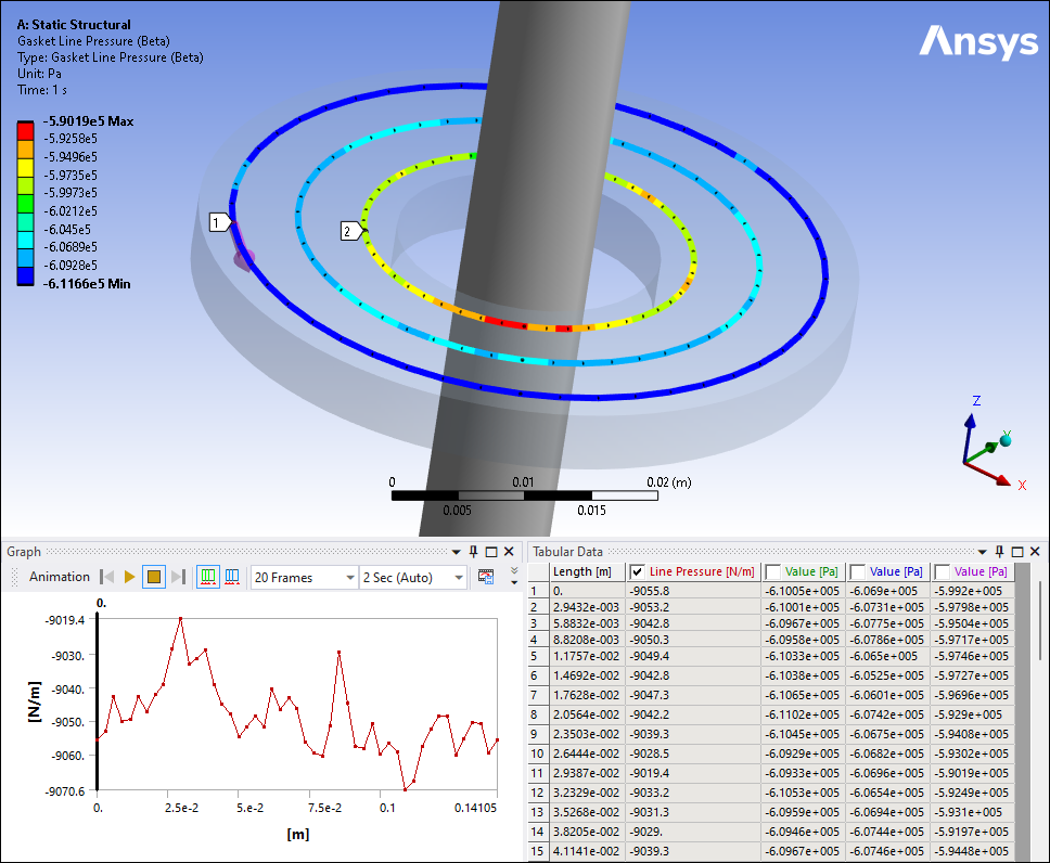
Evaluate Result Values
Here is an example of a Gasket Line Pressure result. Note the available values. The Line Pressure column displays the force created along the center line and each Value columns present the pressure values along each sub-path. The Graphics pane displays the force values at each discretization point.