


First create an Explicit Dynamics system in the Workbench Project Schematic. Open the Properties for the Geometry cell and set the Analysis Type under Advanced Geometry Options to 2D, and create or import an appropriate geometry. For simple 1D wedge analyses consisting of a sphere of explosive surrounded by the ambient material, a sample geometry has been provided with in %AWP_ROOT212%\aisol \Samples\AUTODYN. To use the sample geometry, import the file 1D_wedge_geometry_for_blast.agdb. To change the radius of the explosive material, or the blast radius, modify the parameters ExplosiveMaterialRadius or BlastRadius in DesignModeler.
If you need to create your own geometry, it is important to understand that the geometry of the virtual MME wedge domain that will be created in the Explicit Dynamics solver. This is because the created bodies designed to fill this virtual MME domain must cover the virtual MME domain completely (else there will be void regions).
The wedge domain created in the solver will begin at the global origin and will run along the axis of symmetry (see the following note). The wedge has an angle of 10 degrees. The bodies with Reference Frame set to Eulerian (Virtual) must cover this region in space. An example of an appropriate geometry is shown in Figure 20.1: Appropriate Geometry for a 1D Wedge Analysis.
Note: For users familiar with the Autodyn user interface, in Autodyn 2D axisymmetric models, the axis of symmetry lies along the global X-axis. This is contrary to 2D axisymmetric models in Mechanical, where the axis of symmetry lies along the global Y-axis. Therefore, all Explicit Dynamics 2D axisymmetric models created in Mechanical must be set up assuming the axis of symmetry is along the global Y-axis. This is appropriately handled in the Explicit Dynamics solver by performing a coordinate transformation so that the axis of symmetry is mapped onto the global X-axis.
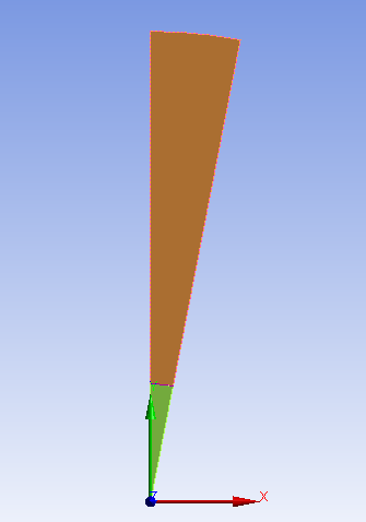
The geometry that makes up the wedge consists of two bodies: one to model the explosive (the smaller green colored body), and the other to model the ambient material in which the explosion is taking place (the larger brown colored body). Be sure that these two bodies do not overlap; otherwise the fill into the Eulerian domain may not be as expected. The coordinate system displayed is the Global Coordinate System. Note how the wedge is aligned with the global Y axis, and that the two bodies together effectively form a sector of a circle centered at the global origin with a 10 degree angle at the center of the sector. The shape shown here will also be the shape of the MME domain.
Once the geometry has been created or imported, the remainder of the model can be set up in Mechanical.
For a 1D wedge analysis, the 2D Behavior of the Geometry must be set to axisymmetric. The bodies need to have the Reference Frame set to Eulerian (Virtual).
You should delete all objects under the Connections folder, including Contact Regions and Body Interaction objects, since the analysis will be purely Eulerian.
Generate the mesh. The default mesh settings should be sufficient.
Insert a Detonation Point at X = 0, Y = 0.
Set the Analysis Settings:
Step Controls:
Time Step Safety Factor = 0.6666.
Solver Controls:
Detonation Burn Type = Program Controlled (for 2D analyses, this defaults to Direct) or Direct.
Euler Domain Controls:
Domain Type = Wedge.
Minimum Y Coordinate = 0. M.
Y Dimension - set to blast radius.
Total Cells - set the total number of cells along the wedge. The resulting cell size will be the Y Dimension divided by the Total Cells. Note that the more cells, the more accurate the simulation, but the longer the run-time. It is recommended that the cell size is such that there are at least 10 cells across the radius of the explosive material.
Note: No grading of the mesh has been exposed at release 2024 R2. This is being considered for a future release.
Output Controls:
Output Remap File – Set this to Program Controlled or On to trigger the output of data files (.fil file format) to be used to remap the solution into a 3D analysis. The frequency of the data files produced is the same frequency as the result file output. The files produced are named remap_{cycle}.fil, where cycle is the cycle number that the data file is produced.
You can set Output Remap Files to On for other Eulerian domain types as long as the 2D Behavior is set to Axisymmetric; otherwise no remap files will be output (Program Controlled regulates this behavior as well).
If there are no Euler domains present in the model, setting Output Remap Files to On is ignored (a warning message is generated).
Prior to using any generated data files for remapping, you should inspect the results in order to ensure that the blast wave has not reached the extents of the wedge at the cycle where the results will be transferred during the remapping. This can be done by inserting User Defined results for variables such as PRESSURE or INT_ENERGYALL, or by adding Pressure or Energy trackers.