- File Type
Use the drop-down menu to set the File Type of File 2 to unv or rst.
- Dimension
The model dimension of the rst file, available options are and . Once you have set the rst file in the File option, this property becomes read-only if your selection and data from the rst file matches, otherwise you will get an error. Default value is .
- Units
The units that quantify the values in the unv file. The default value of Units appears as Dataset 164 in the unv file, which means that the units of the file are input through the units dataset in the file. The rest of the options are intended for unv files without a units dataset, and cover common length units (m, cm, mm, ft, in and µm). In addition, you can define a Custom Length Scale to adjust the dimensions of the unv model with any positive factor. This option is only available for unv files.
- File
Input File 2 using a File dialog. When the file is set, the rest of the File 2 Options are populated, the MAC Frequency Worksheet is populated, the UNV Node Worksheet appears and the File 2 geometry is displayed in the Geometry view. If File 2 is a unv file, its format needs to comply with the restrictions in UNV File Restrictions. Contrary to 2023 R2 and earlier versions, File 2 is not copied to the MAC Calculator subfolder (located in the analysis solver files directory). This setting holds the absolute path to the file and you may therefore need to reload the file if renamed, moved to a new location or deleted.
If the File 2 rst file has a defined cyclic symmetry, the results are automatically expanded.
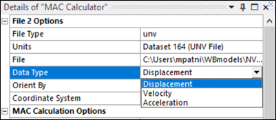
- Data Type
If the File Type is set to
unvthen this property, which contains a list of data type options, is exposed after loading the file. The options available depend on the Specific Data Type set in the unv file under Dataset 55. For instance, if the modal data is available for all the three types, then , and will appear in the drop-down list. Whereas, if only one type is available (displacement, velocity or acceleration), then only that option is selected by default. Note that for MAC calculation purposes, (V) and (A) data from the unv file is converted to (X) data at each eigenvalue (ω) using the following expressions, and is compared against displacement data from the rst file.

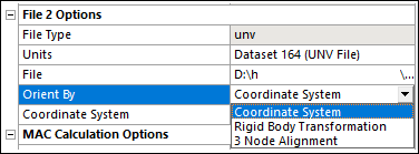
- Orient By
Two options are available to orient the rst file relative to the File 1 model, while three options are available for unv file orientations. Changing any of the options automatically changes the orientation of the File 2 modelin the Geometry view.
- Coordinate System
Supported for both unv and rst files. Orient the unv/rst model according to the RB transformation defined by the center and rotation of a coordinate system defined in the model. The selected coordinate system (CS) should be the one that orients the unv/rst model in the same way that the global coordinate system (GCS) orients the File 1 rst model.
For example, if node A of the File 1 rst file has coordinates (xA,yA,zA) with respect to the GCS, the local CS of the unv/rst File 2 file is the one such that the corresponding unv/rst node to A has coordinates (xA,yA,zA) with respect to the CS.
When Orient By is set to , a Coordinate System property is enabled to select from the coordinate systems defined in the model.
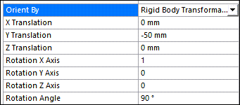
- Rigid Body Transformation
Orient the unv/rst File 2 model according to the RB transformation defined by three translations (X Translation, Y Translation, Z Translation) and three rotations expressed in the axis vector-angle representation (Rotation X Axis, Rotation Y Axis, Rotation Z Axis, Rotation Angle).
The order of the transformations is first Translation, then Rotation. The Rotation Axis does not need to be normalized.
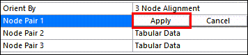
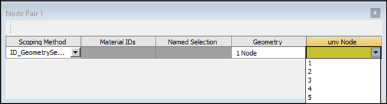
- 3 Node Alignment
Only available for a unv File 2 model. Orient the unv model according to the RB transformation defined by 3 node matches between the rst and unv models. Each Node Pair is defined through a Tabular Data property that is displayed when the property is clicked.
The rst node can be scoped through either a or a . In both cases, the selection can only be formed by one node. The is directly made by graphically picking in the Geometry pane, whereas the is selected through a drop-down menu.
The unv node is selected through a drop-down menu that displays the unv Node Numbers as shown in the UNV Node Worksheet.
The rst-unv node alignment is produced when you press the Apply button in the property field.