VM-LSDYNA-SOLVE-023
VM-LSDYNA-SOLVE-023
I-Shape Beam Deflection Under Uniformly Distributed Loads
Overview
| Reference: | Timoshenko, S.P. (1995). Strength of materials: Part I: Elementary theory and problems. (3rd ed.). D. Van Nostrand Co. p.10. |
| Analysis Type(s): | Implicit Analysis |
| Element Type(s): | Beam (I-shape cross section) |
| Input Files: | Link to Input Files Download Page |
Test Case
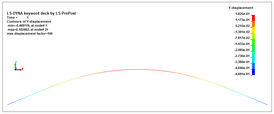
A standard 30 in WF beam with a cross-sectional area A, is supported as shown in Figure 90 and loaded on the overhangs by a uniformly distributed load w. Determine the deflection 𝛅 at the middle of the beam.
This problem is also presented in test case VM2 in the Mechanical APDL Verification Manual.
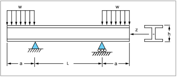
| Material Properties | Geometric Properties | Loading |
|---|---|---|
|
E = 3e7 psi |
L = 240 in a = 120 in h = 30 in A = 50.65 in2 Iz = 7892 in4 |
w = 10000 / 12 = 833.33 lb/in |
Analysis Assumptions and Modeling Notes
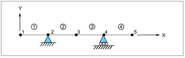
The beam is modeled with beam element elform 2 with an I-shaped cross section (SECTION_01). The geometric parameters for the I-shape cross section are defined as D1 = 15, D2 = 1.0484, D3 = 30.0968, and D4 = 0.6856481. The orientations of the beam elements are defined in the *ELEMENT_BEAM_ORIENTATION card. *LOAD_NODE_POINT is used to apply equal load at each node of the beam overhangs. An implicit analysis is performed to obtain beam deflection.
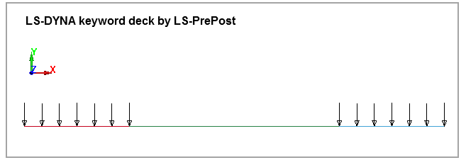
Equal load is applied to the seven nodes at the two beam overhangs as shown in Figure 92. The load applied at each node = w x a/7.