VM2

VM2
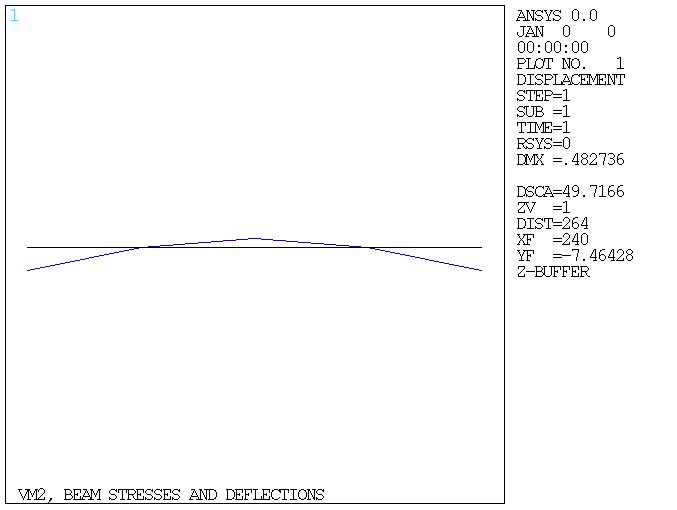
Beam Stresses and Deflections

Overview

Reference: S. Timoshenko, Strength of Material, Part I, Elementary Theory and Problems, 3rd Edition, D. Van Nostrand Co., Inc., New York, NY, 1955, pg. 98, problem 4.
Analysis Type(s): Static Analysis (ANTYPE = 0)
Element Type(s): 3D 2 Node Beam (BEAM188)
Input Listing: vm2.dat

Test Case

A standard 30" WF beam, with a cross-sectional area A, is supported as shown below and loaded on the overhangs by a uniformly distributed load w. Determine the maximum bending stress σ in the middle portion of the beam and the deflection δ at the middle of the beam.

Figure 2: Beam with Cross Section Problem Sketch

Beam with Cross Section Problem Sketch

Material PropertiesGeometric PropertiesLoading
E = 30 x 106 psi
  = 20 ft = 240 in.
a = 10 ft = 120 in.
h = 30 in.
A = 50.65 in2
Iz = 7892 in4
w = 10000 lb/ft = (10000/12) lb/in

Analysis Assumptions and Modeling Notes

An I-section beam is modeled. The width, depth, and thickness of the flanges are chosen to obtain the required area and moment of inertia values. Consistent length units (inches) are used. A half-model could also have been used because of symmetry.

Results Comparison

TargetMechanical APDLRatio
Stress, psi-11400.000-11440.7461.004
Deflection, in0.1820.1821.003
  1. occurs at the bottom flange of the beam

Figure 3: Displaced Geometry Display

Displaced Geometry Display