


VM-LSDYNA-SOLVE-019
VM-LSDYNA-SOLVE-019
Long Bar with Compressive Load
Overview
| Reference: | Any solid mechanics textbook |
| Analysis Type(s): | Linear Static Structural Analysis |
| Element Type(s): | Beam |
| Input Files: | Link to Input Files Download Page |
Test Case
This test case also appears in the Workbench Mechanical Verification Manual. See VM-WB-MECH-009.
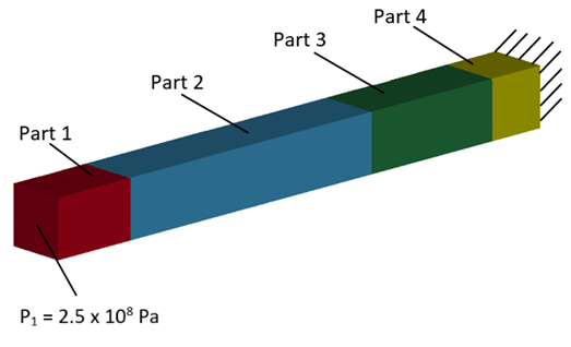
A multibody of four bars connected end to end has one end face fixed and a pressure of 2.5 x 10⁸ Pa applied to the opposite face. The material and geometric properties of the multibody are given in the table below.
Find the maximum equivalent stress for the whole multibody and the safety factor for each part using the maximum equivalent stress theory with tensile yield limit.
Find the maximum equivalent stress for the whole multibody and the safety factor for each part using the maximum equivalent stress theory with tensile yield limit.
| Material Properties | Geometric Properties | Loading |
|---|---|---|
|
Part 1: E = 1.93 x 10¹¹ Pa, v = 0, Tensile Yield = 2.07 x 10⁸ Pa |
Part 1: 2 m x 2 m x 3 m | P1 = 2.5 x 10⁸ Pa |
|
Part 2: E = 7.1 x 10¹¹ Pa, v = 0, Tensile Yield = 2.8 x 10⁸ Pa |
Part 2: 2 m x 2 m x 10 m | – |
|
Part 3: E = 2.0 x 10¹¹ Pa, v = 0, Tensile Yield = 2.5 x 10⁸ Pa |
Part 3: 2 m x 2 m x 5 m | – |
|
Part 4: E = 1.1 x 10¹¹ Pa, v = 0, Tensile Yield = 2.8 x 10⁸ Pa |
Part 4: 2 m x 2 m x 2 m | – |
Analysis Assumptions and Modeling Notes
The multibody is made of beam elements using ELFORM 1 with 2x2 Gauss quadrature and thickness 2 m in y and z-directions. Each part uses *MAT_PLASTIC_KINEMATIC with varying material properties.
*BOUNDARY_SPC_NODE is used to constrain one end of the multibody. A compressive force of 1 x 10⁹ Pa is described using *DEFINE_CURVE and prescribed to the opposite face using *LOAD_NODE. *DAMPING_GLOBAL was added with VALDMP set to 200 to define mass weighted nodal damping. BEAMIP was set to 4 in *DATABASE_EXTENT_BINARY to specify the number of beam integration points to output to d3plot per element.
The Safety Factor is defined as the yield strength over the maximum effective stress:

Results Comparison
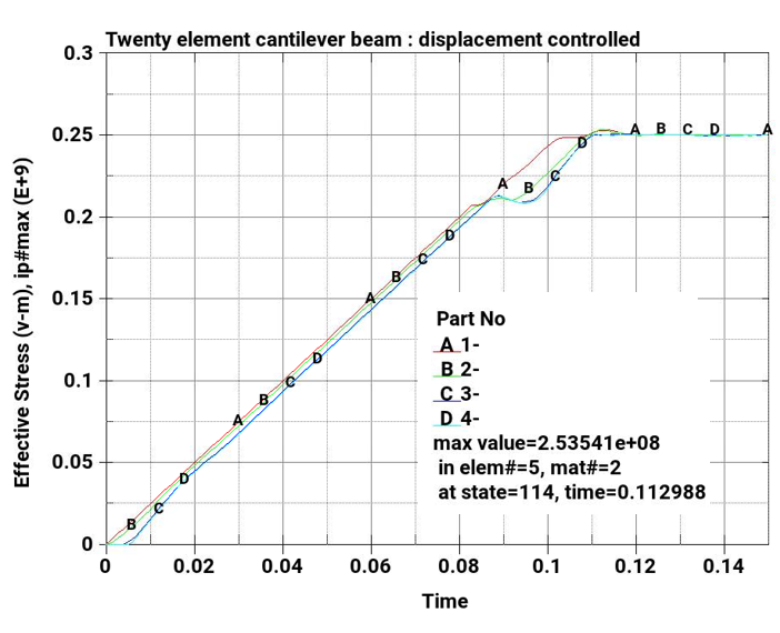
The following plot shows the max effective stress in each part of the multibody. In all parts, the max effective stress and Safety Factor correspond to their respective target.
| Results | Target | LS-DYNA | Error (%) |
|---|---|---|---|
| Maximum Equivalent Stress (Pa) | 2.5 x 10⁸ | 2.5 x 10⁸ | 0.0 |
| Safety Factor of Part 1 | 0.828 | 0.828 | 0.0 |
| Safety Factor of Part 2 | 1.12 | 1.12 | 0.0 |
| Safety Factor of Part 3 | 1 | 1 | 0.0 |
| Safety Factor of Part 4 | 1.12 | 1.12 | 0.0 |