VM-LSDYNA-SOLVE-018
VM-LSDYNA-SOLVE-018
3D Shear Failure Test (Cubes)
Overview
| Reference: | Any solid mechanics textbook |
| Analysis Type(s): | Explicit Dynamics 3D |
| Element Type(s): | Solid, Hexahedral and Tetrahedral Elements |
| Input Files: | Link to Input Files Download Page |
Test Case
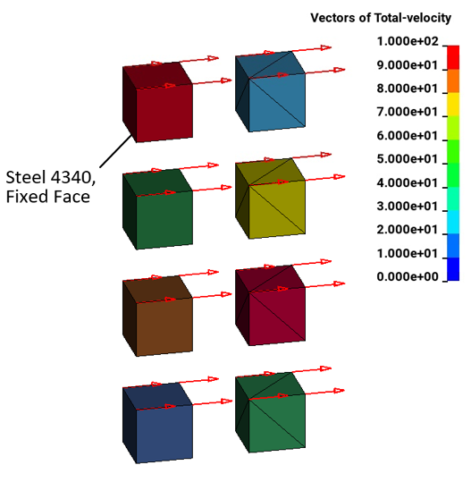
This problem tests the tensile pressure failure, plastic strain failure, shear stress failure, and shear strain failure of 8-node linear interpolated reduced integration constant stress hexahedral elements, and reduced integration tetrahedral elements subjected to pure shear.
Four hex-part/tet-part pairs are each assigned a different material. All four materials use Steel 4340, but with different failure criteria. From top to bottom, the failure criteria are:
Tensile pressure failure at a maximum tensile pressure = -3 x 10¹⁰ Pa
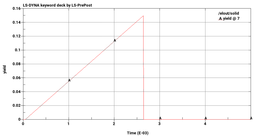
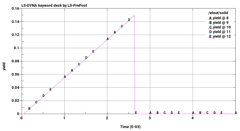
Plastic strain failure at strain = 0.15
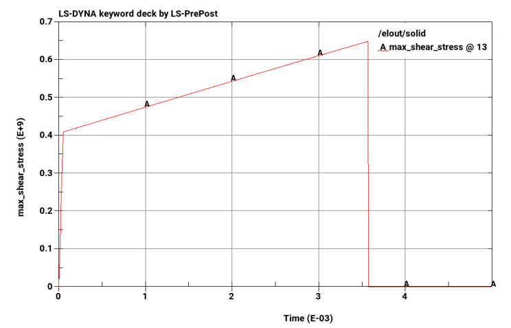
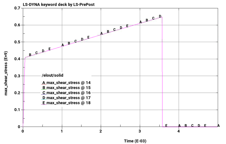
Shear stress failure at a maximum shear stress of 6.5 x 10⁸ Pa
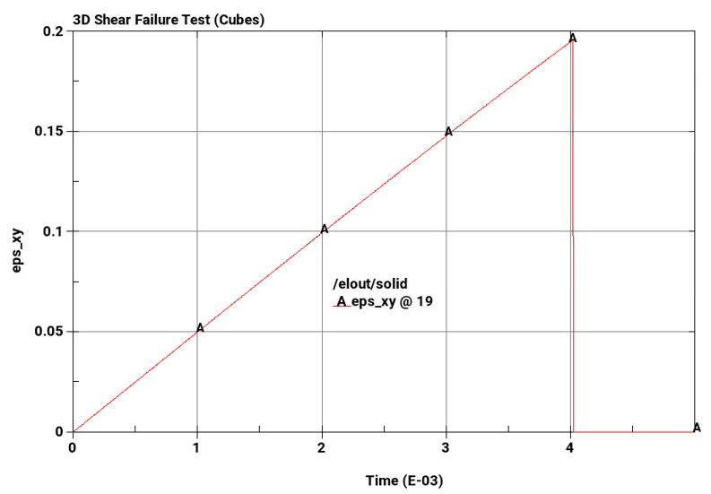
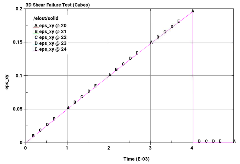
Shear strain failure at a maximum shear strain of 0.2
The bottom boundary of each cube has a fixed constraint. The top boundary of each cube is constrained to translation in the x-direction. A constant x-velocity of 100 m/s is applied to the top boundary of each cube. The calculation is run with a fixed time step of 5E–6 s for 1000 cycles.
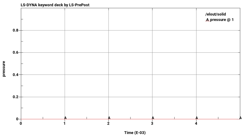
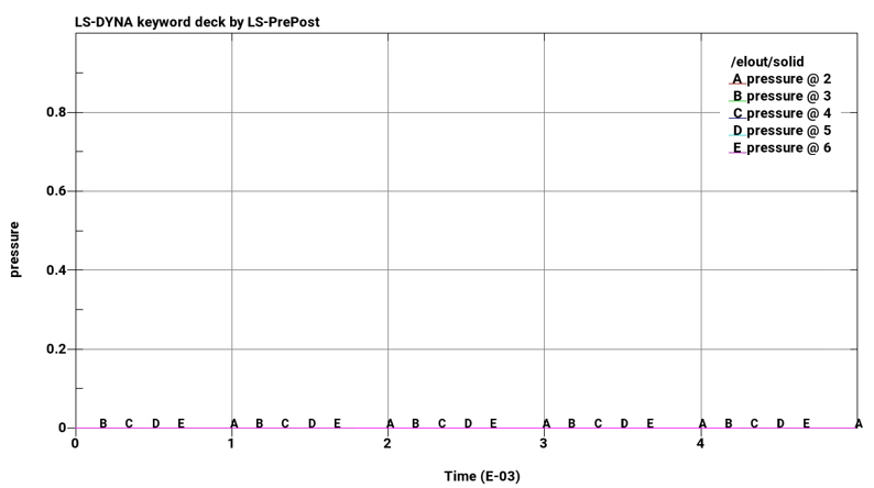
Plot element pressure, effective plastic strain, maximum shear stress, and maximum shear strain vs. time for the pairs of cubes from top to bottom.
| Material Properties | Geometric Properties | Loading |
|---|---|---|
| E = 2.07 x 10¹¹ Pa | L1 = L2 = L3 = L4 = 1 m | vr = 100 m/s |
| v = 0.29 | – | – |
| σyield = 7.10 x 10⁸ Pa | – | – |
Analysis Assumptions and Modeling Notes
The load curve LCTM in *CONTROL_TIMESTEP defines the constant timestep of 5 x 10⁻⁶ seconds. Hex elements use ELFORM 1, while tets use ELFORM 10. *DATABASE_ELOUT, *DATABASE_EXTENET_BINARY, and *DATABASE_HISTORY_SOLID_SET were used to monitor element stresses and strain.
Steel 4340 material properties were defined using *MAT_PLASTIC_KINEMATIC. Failure Criteria for each hex and tet set were defined in *MAT_ADD_EROSION. *BOUNDARY_SPC_SET was used to define boundary constraints on the top and right bottom of the cubes. *BOUNDARY_PRESCIRBED_MOTION with DOF equal to 1, VAD equal to 0, and LCID as time history of velocity describes the x-velocity on the top face of each cube.
Results Comparison
The following plots show pressure, effective plastic strain, maximum shear stress, and maximum shear strain vs. time for the pairs of cubes from top to bottom. The plots on the left are of hex elements, while plots on the right are of tet elements. Stress and strain drop to zero on element failure due to *MAT_ADD_EROSION, which causes the elements to erode once failure criteria is met. In all cases, failure points correspond to defined failure limits.