VM-LSDYNA-SOLVE-015
M-LSDYNA-SOLVE-015
Implicit Deflection of Cantilever due to Temperature Variation
Overview
| Reference: | Kreith, F. (1959). Principles of Heat Transfer (2nd ed.). International Textbook Co. |
| Analysis Type(s): | Thermal Structure |
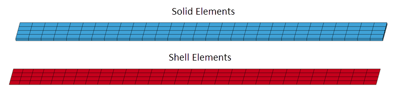
| Element Type(s): | Shell, Solid |
| Input Files: | Link to Input Files Download Page |
Test Case
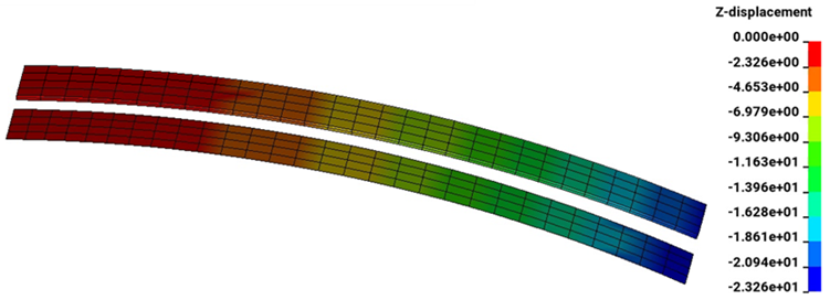
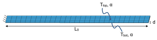
A cantilever beam with Length L = 107 m and thickness 0.75 m is fixed at one end. The temperature on the top and bottom surfaces raise from 0°C to 100°C and 0°C to 50°C, respectively, over the course of one second. The beam has a constant thermal expansion coefficient with temperature, α = 6x10⁻⁵°C-1. Find the z-deflection b at the end of the beam due to the temperature variation at t = 1 s.
| Material Properties | Geometric Properties | Loading |
|---|---|---|
| k = 1000 W/(m° C) | L = 107 m | T0, top = 0° C |
| α = 6E-5° C-1 | d = 0.75 m | Tf, top = 100° C |
| – | – | T0, bot = 0° C |
| – | – | Tf, bot = 50° C |
Analysis Assumptions and Modeling Notes
LS-DYNA Thermal Solver 11 is used. SOLN is set to 2 in *CONTROL_SOLUTION to specify coupled structural thermal analysis. *CONTROL_IMPLCIT_GENERAL is used to specify implicit analysis with an initial timestep of 0.1 s. Two cantilever models were used for this problem.
One uses solid elements with ELFORM 1, constant stress. Hourglass control type 6 is used. The cantilever is three solid elements thick.
The other model uses shell elements with ELFORM 16. Hourglass control type 8 is used. The element thickness is 0.75 m. The transverse shear correction factor is set to the recommended 0.833 in *SECTION_SHELL. Three integration points are used through the thickness of the shell elements by setting NIP to 3. TSHELL is set to 1 in *CONTROL_SHELL to treat shell elements as 12-node brick elements to allow conduction through shell thickness. IRQUAD is set to 2 for 2x2 gauss quadrature as the in-plane integration rule.
Both models use *MAT_ELASTIC_PLASTIC_THERMAL to define the thermal expansion coefficient as a function of temperature. *MAT_THERMAL_ISOTROPIC is used for thermal property identification. Initial and final temperatures of the top and bottom surfaces of the cantilever are defined in *BOUNDARY_TEMPERATURE. Geometric boundary constraints are made using *BOUNDARY_SPC_NODE.
It is assumed that temperature varies linearly through beam thickness d.
Consider the equation for beam curvature due to temperature variation:

Integrating twice with respect to x, we get the equation for cantilever deflection due to temperature variation:

With boundary conditions, at x = 0 m:

Applying boundary conditions, c1 and c2 are determined to be equal to zero. Plugging in the known variables, we get the analytical solution for beam deflection, b = 22.89 m