

VM-LSDYNA-BENCHMARK-007
VM-LSDYNA-BENCHMARK-007
Indentation of a Semi-Rigid Long Cylinder in an Elastic, Perfectly Plastic
Half-Space
Overview
| Reference: | Jackson, R. L. (2018). A solution of rigid perfectly plastic cylindrical indentation in plane strain and comparison to elastic-plastic finite element predictions with hardening. Journal of Applied Mechanics, 85 (2). |
| Analysis Type(s): | Explicit Dynamics with Workbench LS-DYNA |
| Element Type(s): | Solid |
| Input Files | Link to Input Files Download Page |
Test Case
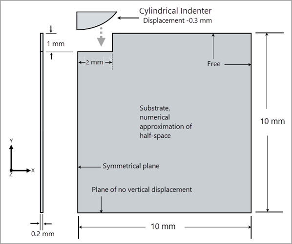
A semi-rigid, long, cylinder is pressed into a half-space (approximated by a parallelogram) having isotropic, elastic, perfectly plastic, mechanical properties. The indentation causes plastic deformation of the half-space. The half-space was modeled with Young's modulus (E) of 200 GPa, Poisson's ratio of 0.3, and a yield strength of 200 MPa. The semi-rigid indenter was modeled with Young's modulus (E) of 2.0E+6 GPa and Poisson's ratio of zero.
| Material Properties | Geometric Properties | Loading |
|---|---|---|
|
E1 = 200 GPa ν = 0.3 |
L = 50 in B = 2 in H = 2 in | Disp Y = 3.0E-4 m |
Analysis Assumptions and Modeling Notes
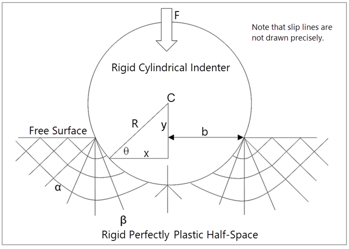
The closed form solution using slip line theory is discussed in the reference. Given an indentation depth, the length of the indentation mark on the top free surface of the half-space (along the x-direction) and the force on the indenter can be calculated using a closed form solution as shown in Figure 245: Slip Line Theory and the equation below:
 | (41) |
In the above equation, F is the force on the indenter, R is the radius of the indenter, Sy is the yield strength, L is the thickness of the simulation domain which is also the length of the indenter, and b is the size of the indent along the X direction on the top free surface of the indenter.
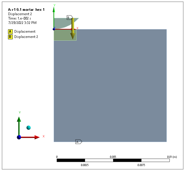
For LS-DYNA simulations (Explicit), AUTOMATIC_SURFACE_TO_SURFACE contacts were used with the MORTAR option.
The half-space was discretized in two separate regions. The region away from the indenter was meshed by prescribing an element size of 0.25 mm which was not changed. The indenter and the small 2 x 1 x 0.2 mm region under the indenter were meshed according to the prescribed convergence values.
The load application was defined over 0.01 seconds.
The element used was LS-DYNA Explicit Hex 1 with a mesh size of 0.1 mm.
Results Comparison values are reported for the Windows 11 platform.
Results Comparison
| Results | Target | Workbench LS-DYNA | Error (%) |
|---|---|---|---|
|
Equivalent Stress Max (σeq, MPa) | 200.0 | 200.0 | 0.0 |
|
Normal Stress Max (σnorm, MPa) | 26.96 | 26.71 | –0.91 |
|
Directional Def X1 Max (u, mm) | 0.169 | 0.170 | 0.225 |
|
Directional Def X2 Max (u, mm) | 0.00744 | 0.00744 | 0.00 |
|
Shear XY Max (τxy, MPa) | 757.13 | 746.164 | –1.448 |
|
Total strain intensity (EPTOINT Max) | 0.13356 | 0.13356 | 0.0 |
|
Deformation X Max (u, mm) | 0.16851 | 0.1691 | 0.2314 |