


*CONTACT_AUTOMATIC_GENERAL
Specifies friction or frictionless contacts between line bodies (beams). This keyword is created if the contact is specified using Body Interactions and the geometry contains line bodies.
All the parameter cards are the same as in *CONTACT_AUTOMATIC_SINGLE_SURFACE.
*CONTACT_AUTOMATIC_NODES_TO_SURFACE
Specifies nodes-to-surface friction or frictionless contacts. This keyword is created if the contact is specified using a Contact Region and the Behavior is set to Asymmetric .
Card1 - mandatory
SSID = ID for the set of contact nodes involved in the contact.
MSID = ID for the set of target segments involved in the contact.
SSTYP = 4, the contact entities for the contact are nodes or SPH particles.
MSTYP = 0, the target entities for the contact are segments.
SBOXID, MBOXID, SPR and MPR are the same as in *CONTACT_AUTOMATIC_SINGLE_SURFACE.
Parameter Card2 and Card3 is the same as in *CONTACT_AUTOMATIC_SINGLE_SURFACE.
*CONTACT_AUTOMATIC_SINGLE_SURFACE
Specifies friction or frictionless contacts between parts. This keyword is created if the contact is specified using Body Interactions .
Card1 - mandatory
SSID = ID for the set of parts created for the bodies in the Body Interaction . If the contact is applied to all the bodies in the geometry then this parameter is set to 0.
MSID = 0.
SSTYP =2, the contact entities are parts. If the contact is applied to all the bodies in the geometry then this parameter is set to 5.
MSTYP = 2, the target entities are parts. If the contact is applied to all the bodies in the geometry then this parameter is set to 0.
SBOXID = It is not used, will be left blank.
MBOXID = It is not used, will be left blank.
SPR = 1 (constant) requests that forces on the contact side of the contact be included in the results files NCFORC (ASCII) and INTFOR (binary).
MPR = 1 (constant) requests that forces on the target side of the contact be included in the results files NCFORC (ASCII) and INTFOR (binary). T
Card2 - mandatory
FS = Friction Coefficient value from the inputs for frictional contact.
FD = Dynamic Coefficient value from the inputs for frictional contact.
DC = Decay Constant value from the inputs for frictional contact.
VC = 0 (LS-DYNA default).
VDC = 10 (constant). This parameter specifies the percentage of the critical viscous damping coefficient to be used in order to avoid undesirable oscillation in the contact.
Card3 - mandatory, left blank for defaults to be used.
Card A is the same as for *CONTACT_AUTOMATIC_SURFACE_TO_SURFACE.
*CONTACT_AUTOMATIC_SURFACE_TO_SURFACE
Defines specific surface-to-surface friction or frictionless contacts. This keyword is created if the contact is specified using a Contact Region and the Behavior is set to Symmetric .
Card1 - mandatory
SSID = ID for the set of contact segments involved in the contact.
MSID = ID for the set of target segments involved in the contact.
SSTYP = 0, the contact entities for the contact are segments.
MSTYP = 0, the target entities for the contact are segments.
SBOXID, MBOXID, SPR and MPR are the same as in *CONTACT_AUTOMATIC_SINGLE_SURFACE.
Parameter Card2 and Card3 are the same as in *CONTACT_AUTOMATIC_SINGLE_SURFACE.
Card A
SOFT = 2 except for asymmetric contacts like NODES_TO_SURFACE and unbreakable bonded contacts for which it is set to 1.
SOFSCL = left blank, the default value of 0.1 will be used. This scale factor is used to determine the stiffness of the interface when SOFT is set to 1. For SOFT = 2 scale factor SLSFAC (see *CONTROL_CONTACT) is used instead.
LCIDAB = left blank.
MAXPAR= left blank.
SBOPT = 3.
DEPTH = 5.
*CONTACT_AUTOMATIC_SURFACE_TO_SURFACE_TIEBREAK
Specifies breakable symmetric bonded contacts. This keyword is created for Bonded contact when the Breakable option is set to Stress Criteria and the contact Behavior is set to Symmetric .
Card 1 is the same as in *CONTACT_TIED_SURFACE_TO_SURFACE_OFFSET.
Card2 - mandatory
FS = Normal Stress Limit value for the bonded contact.
FD = Shear Stress Limit value for the bonded contact.
DC = 0 (LS-DYNA default). This parameter is not required for bonded contacts.
VC and VDC are the same as in *CONTACT_AUTOMATIC_SINGLE_SURFACE.
Card3 - mandatory, is left blank.
Card A is the same as for *CONTACT_AUTOMATIC_SURFACE_TO_SURFACE.
*CONTACT_ONEWAY_AUTOMATIC_SURFACE_TO_SURFACE_TIEBREAK
Specifies breakable asymmetric bonded contacts. This keyword is created for Bonded contact when the Breakable option is set to Stress Criteria and the contact Behavior is set to Asymmetric .
Parameter cards are the same as in *CONTACT_AUTOMATIC_SURFACE_TO_SURFACE_TIEBREAK.
Card A is not used for this keyword.
*CONTACT_TIED_NODES_TO_SURFACE_OFFSET
Specifies non-breakable asymmetric bonded contacts. This keyword is created for Bonded contacts that are not designated as Breakable whose Behavior is set to Asymmetric . This keyword is not used for Body Interactions as these types of contacts are always symmetric.
Card1 - mandatory
SSID = ID for the set of contact nodes involved in the contact.
MSID = ID for the set of target segment or for the set of parts involved in the contact.
SSTYP = 4. SSID indicates the ID for a set of nodes.
MSTYP = 0, MSID indicates the ID for a set of segments.
SBOXID, MBOXID, SPR and MPR are the same as in *CONTACT_AUTOMATIC_SINGLE_SURFACE.
Card 2 left blank.
Card 3
SFS = left blank, the default value of 1.0 will be used. Default contact penalty stiffness scale factor for SLSFAC (see *CONTROL_CONTACT).
SFM= left blank, the default value of 1.0 will be used. Default target penalty stiffness scale factor for SLSFAC (see *CONTROL_CONTACT).
SST = the negative value of:
"Maximum Offset" is the Definition parameter available for bonded contacts and body interactions. "Maximum Offset" is obtained from the inputs of the Contact Region of Bonded type.
MST = SST.

*CONTACT_TIED_NODES_TO_SURFACE_CONSTRAINED_OFFSET
Specifies non-breakable asymmetric bonded contacts. This keyword is created for Bonded contacts that are not designated as Breakable whose Behavior is set to Asymmetric and when the contact Formulation is set to MPC. This keyword is not used for Body Interactions as these types of contacts are always symmetric.
The card is identical to CONTACT_TIED_NODES_TO_SURFACE_ OFFSET.
*CONTACT_TIED_SURFACE_TO_SURFACE_OFFSET
Specifies general non-breakable bonded contacts that are symmetric. This keyword is created for Bonded and non-breakable contacts which are defined by Contact Regions that are Bonded , non-breakable and whose Behavior is set to Symmetric .
Card1 - mandatory
SSID = ID for a set of contact segments or a set of parts involved in the contact.
MSID = ID for the set of target segments or the set of parts involved in the contact.
SSTYP = specifies whether the ID used in SSID represents parts or segments. It is set to 0 if SSID represents a set of segments and 2 if it represents a set of parts.
MSTYP = SSTYP.
SBOXID, MBOXID, SPR and MPR are the same as in *CONTACT_AUTOMATIC_SINGLE_SURFACE.
Cards 2 and 3 are the same as in *CONTACT_TIED_NODES_TO_SURFACE_OFFSET.
Card A is the same as for *CONTACT_AUTOMATIC_SURFACE_TO_SURFACE.
*CONTACT_TIED_SURFACE_TO_SURFACE_CONSTRAINED_OFFSET
Specifies general non-breakable bonded contacts that are symmetric. This keyword is created for Bonded and non-breakable contacts which are defined by Contact Regions that are Bonded, non-breakable and whose Behavior is set to Symmetric and when the contact Formulation is set to MPC.
The card is identical to CONTACT_TIED_SURFACE_TO_SURFACE_ OFFSET.
*CONSTRAINED_SPOTWELD
Specifies spot welds between non-contiguous nodal pairs of shell elements. This keyword is created when a spot weld contact is defined in the Mechanical application.
Card
N1 = ID of the first node used in the weld.
N2 = ID of the second node present in the weld.
SN = Normal force at weld failure.
SS = Shear force at weld failure.
N = Exponent of normal force.
M = Exponent of shear force.
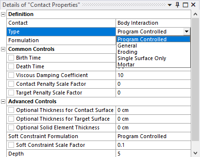
The Contact Properties object found on the LSDYNA Pre tab allows you to modify the default generated values (the type of the contact) and specify additional values.
*CONTACT_ERODING_SINGLE_SURFACE is written if the contact is specified using a body interaction.
The following keywords are written if the contact is specified using a contact region, and the indicated conditions exist.
*CONTACT_ERODING_NODES_TO_SURFACE is written if the Contact Properties Type field is set to Eroding and the contact is asymmetric.
*CONTACT_ERODING_SURFACE_TO_SURFACE is written if the Contact Properties Type field is set to Eroding and the contact is symmetric.
*CONTACT_FORMING_SURFACE_TO_SURFACE is written if the Contact Properties Type field is set to Forming and the contact is symmetric.
*CONTACT_FORMING_ONE_WAY_SURFACE_TO_SURFACE is written if the Contact Properties Type field is set to Forming and the contact is asymmetric.
*CONTACT_FORMING_NODES_TO_SURFACE is written if the Contact Properties Type field is set to Forming and the contact is asymmetric, and the scoped entities on the contact side are edges.
*CONTACT_INTERFERENCE_SURFACE_TO_SURFACE is written if the Contact Properties Type field is set to Interference and the contact is symmetric.
*CONTACT_INTERFERENCE_ONE_WAY_SURFACE_TO_SURFACE is written if the Contact Properties Type field is set to Interference and the contact is asymmetric.
*CONTACT_INTERFERENCE_NODES_TO_SURFACE is written if the Contact Properties Type field is set to Interference and the contact is asymmetric, and the scoped entities on the contact side are edges.
*CONTACT_TIED_SHELL_EDGE_TO_SURFACE is written if the Contact Properties Type field is set to Tied Shell Edge, the contact is asymmetric, and the contact formulation is set to MPC.
*CONTACT_TIED_SHELL_EDGE_TO_SURFACE_BEAM_OFFSET is written if the Contact Properties Type field is set to Tied Shell Edge, the contact is asymmetric. This is the default behavior.
*CONTACT_AUTOMATIC_SURFACE_TO_SURFACE_MORTAR_TIED is written if the Contact Properties Type field is set to Mortar and the contact is symmetric, bonded, and non breakable.
*CONTACT_AUTOMATIC_SURFACE_TO_SURFACE_TIEBREAK_MORTAR is written if the Contact Properties Type field is set to Mortar and the contact is symmetric and breakable.
*CONTACT_AUTOMATIC_SURFACE_TO_SURFACE_MORTAR is written if the Contact Properties Type field is set to Mortar and the contact is symmetric.
*CONTACT_AUTOMATIC_SINGLE_SURFACE_MORTAR is written if the contact is specified using a Body Interaction and the Contact Properties Type field is set to Mortar.
The cards for these contact keywords are as follows:
Card1
BT = Birth Time from the Common Controls section of the Contact Properties object.
DT = Death Time from the Common Controls section of the Contact Properties object.
SFS = Contact Penalty Scale Factor from the Common Controls section of the Contact Properties object.
SFM = Target Penalty Scale Factor from the Common Controls section of the Contact Properties object.
SST = Optional Thickness for Contact Surface from the Advanced Controls section of the Contact Properties object.
MST = Optional Thickness for Target Surface from the Advanced Controls section of the Contact Properties object.
DEPTH = Depth from the Advanced Controls section of the Contact Properties object.
Card A is also modified
SOFT = Soft Constraint Formulation from the Advanced Controls section of the Contact Properties object.
SOFTSCL = Soft Constraint Scale Factor from the Advanced Controls section of the Contact Properties object.
If the contact type is set to Eroding, additional parameters are available to support this formulation.
ISYM = Symmetry Plane Option from the Erosion Controls section of the Contact Properties object.
IADJ = Erosion Node Option from the Erosion Controls section of the Contact Properties object.
EROSOP = Solid Elements Treatment from the Erosion Controls section of the Contact Properties object.
*CONTACT_FORCE_TRANSDUCER_PENALTY
When single surface contacts are used, one or more force transducers are added via
the
*CONTACT_FORCE_TRANSDUCER_PENALTY
command. A force transducer does
not produce any contact forces and allows you to monitor the contact forces on a
subset of parts of the models.
A force transducer is added for each body involved in a body interaction (Frictionless or Frictional).