- General Parameters
- Ignore size
ignores sliver surfaces with an edge that is smaller than the defined value by merging the smaller loop with the adjacent loop.
- Respect line elements
forces the surface mesher to respect nodes from given line elements on curves instead of creating new nodes. This is useful to connect a mesh to an existing mesh.
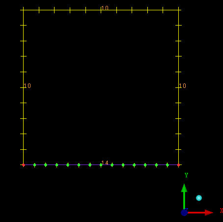
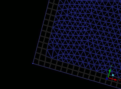
In Figure 244: Line Element Generated, a curve of element count 14 was meshed and a line element was generated.
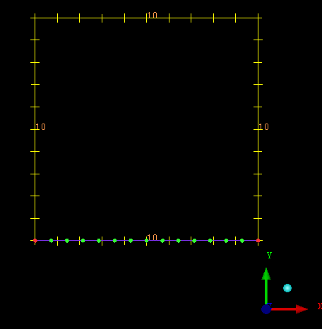
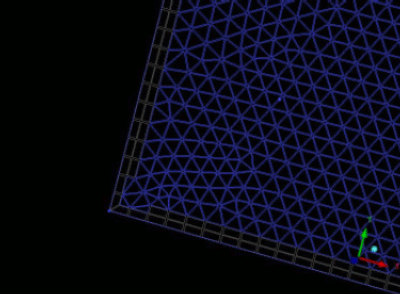
In Figure 245: Line Element Count Changed, the element count was changed from 14 to 10.
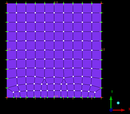
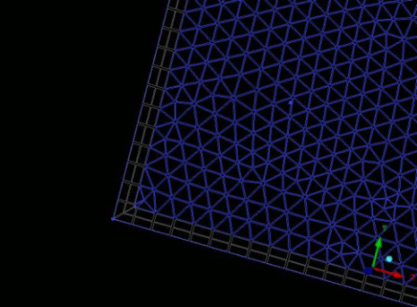
If the four curves are chosen for Patch based surface meshing, and Respect line elements is enabled, line element mesh will remain intact. The resulting mesh is shown in Figure 246: Respect Line Elements Enabled.
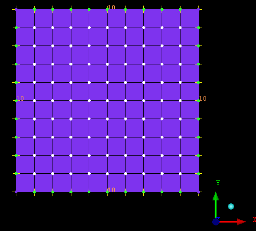
When Respect line elements is disabled, the surface mesh created has ignored the line element mesh and readjusted the mesh on the curves based on the element count, as shown in Figure 247: Respect Line Elements Disabled.
Respect line elements is useful to make sure that new mesh matches and connects with an existing mesh. This is particularly useful if the existing mesh came from another mesher, such as Ansys ICEM CFD Hexa mesher, or from an outside product. This option is also helpful if there is a complex edge distribution that would be hard to match with the curve parameter controls.
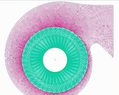
In the example in Figure 248: Example of Respect Line Elements Option, the inner fan was meshed using the Ansys ICEM CFD Hexa mesher and the outer shroud was meshed with Respect line elements to create a node for node conformal mesh.
- Quadratic elements
when enabled, generates the patch dependent surface mesh with mid side nodes (quadratic elements), such that triangles have 6 nodes (3 corners and 3 mid side nodes) and quads have 8 nodes (4 corners and 4 mid side nodes). The mid side nodes are projected to the surface and the resulting edge shape is quadratic (rather than linear). When this option is disabled, the patch dependent surface mesh consists of linear triangles and quads, each with 3 or 4 corner nodes, respectively.
Note: Typically FEA solvers prefer quadratic elements. Most CFD solvers do not support quadratic elements at all.
- Boundary Parameters
- Protect given line elements
is available when Ignore size is set and Respect line elements is enabled in the General section of the Shell Meshing Parameters list. If enabled, it will protect existing line elements that are smaller than the Ignore size value from being removed.
- Smooth boundaries
smooths the surface mesh boundaries after meshing. This will typically give better quality mesh, but it may not respect the initial node spacing.
- Allow free bunching
if enabled, it allows free bunching for patch independent (Octree, with or without Tetra) surfaces. If disabled, curve bunching is done by the Patch Dependent mesher and respected by Patch Independent functions.
- Offset type
- Standard
Offsets will be created normal to the edges without special solutions for sections with small or large angles, such as corners. The number of nodes on the offset front may not be identical as the number of nodes on the initial boundary.
- Simple
Offsets will be created normal to the edges without special solutions for sections with small or large angles, such as corners. The number of nodes on the offset front is identical to the number of nodes on the initial boundary.
- Forced Simple
This option is the same as simple offset, but without collision checking.
- Interior Parameters
- Force Mapping
If the boundary is nearly quadrilateral, the mesher forces the generation of structured mesh instead of unstructured mesh up to this specified block quality. Default value is 0. For hybrid meshes a value of 0.2 is preferred.
- Max nodes adjustment
For opposite boundaries with differing node counts, this function will calculate the ratio of the node counts as a percentage. For all ratio percentage values less than this specified value, mapping will be applied to the mesh. For all ratio percentage values greater than this specified value, mapping will not be applied.
- Project to surfaces
If enabled, it will allow the mesher to project the mesh to the surface.
Note: Disable this if the geometry does not have surfaces.
- Adapt mesh interior
Uses the surface sizes to coarsen the mesh internally. For example, if curve size is set to 1, and surface size to 10, then the mesh will start with a mesh size of 1 on the curves, but transition to 10 in the middle of the surface. This is more effective on larger surfaces where the element reduction is more dramatic.
The default growth rate for the transition to the surface max size is 1.5. This growth rate can be adjusted by setting the surface Height Ratio to between 1.0 and 3. Sizes below 1.0 are inverted (for example, 0.667 becomes 1.5). Sizes above 3 are ignored and the default is used. If this option is enabled, Force Mapping is disabled on surfaces whose maximum size setting exceeds its perimeter curve sizes by a factor of 2 or more.
The difference in the transition rate is shown in Figure 252: Example of Adapt Mesh Interior option:
Figure 252: Example of Adapt Mesh Interior option
Adapt Mesh Interior option disabled 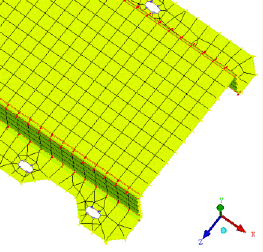
Adapt Mesh Interior option enabled Default Surface Height Ratio = 1.5 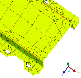
Surface Height Ratio = 3 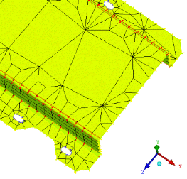
Note: The Max Element size specified in the General Parameters takes precedence over this value.
Note: For All Quad, Quad Dominant, and Quad with one Tri mesh, the Force Mapping option has priority over this option. To apply the Adapt mesh interior option to these types of mesh, set the Force Mapping value to 0.
- Orient to surface normals
orients the shell normals in the same direction as the surface normals. This option is enabled by default.
- Repair Parameters
- Try harder
Level 0
If the mesher fails, no further meshing step is tried. The problem(s) will be reported.
Level 1
If the mesher fails, simple triangulation is attempted to fix the problems (for "All Tri" and "Quad Dominant" mesh types only).
Level 2
All Level 1 steps will be completed. If necessary, all Level 1 steps will be retried without merging at dormant curves.
Level 3
All Level 2 steps will be completed. If necessary, surface meshing will be retried with the Tetra mesher.
- Improvement level
Level 0 does pure Laplacian smoothing. Nodes are moved while keeping the mesh topology unchanged.
Level 1 will mesh any failed loop with an STL method if element types Quad Dominant or All Tri has been selected. This makes the mesher more robust. Very bad quadrangles will be split into triangles.
Level 2 will operate as Level 1, and also will combine triangles to quadrangles and will split more bad quadrangles into triangles. This option is most used.
Level 3 will operate as Level 2, and also will move nodes off curves to improve the quality.
- Respect dormant boundaries
If enabled, all dormant curves and points are included in the mesh boundary definitions. The default is off.
- Relax dormant boundaries for smoothing
If Mesh dormant is enabled, then this option allows nodes on dormant curves and points to be moved in order to improve smoothing.


