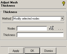
 The Assign Mesh Thickness options available are shown in Figure 478: Adjust Mesh Thickness Options
Note: Uniform shell thickness can also be applied under , but that definition is stored in an attribute file and not in the mesh. Thickness applied here becomes the default when setting up properties for 2D elements. Variable thickness should always be applied here before defining 2D element properties.
- Method
Calculate
Mesh thickness will be assigned automatically to each node of the surface element from the thickness information stored on the surface geometry at that location. This thickness can come automatically from the midsurfacing process (including varying thickness) or be applied manually with > .
The thickness is defined normal to the surface in both directions. The thickness can be viewed from the display tree by right-clicking > > .
- Calculate from solid
allows you to extract the thickness information of shell elements from the solid geometry around the shells. This is used when the midsurface thickness information is not present on the surfaces. To use this, load the original solid geometry. The shells mesh should be within this geometry. Select the part of the solid to calculate the thickness. This method uses the nearest point projection for thickness calculation. The average of the thickness in both directions is used for each node.
- Piercing
is an alternative method for calculating the thickness from a solid. It may be preferable for surfaces with greater thickness where the nearest point method may not be appropriate.
Note: The nearest point projection and piercing methods lead to similar results for surfaces with small thickness.
Remove
Removes the mesh thickness assigned to the nodes of the surface elements.
Modify selected nodes
Individual nodes of surface element can be assigned a specified thickness.


