


The allow you to set geometry preferences.
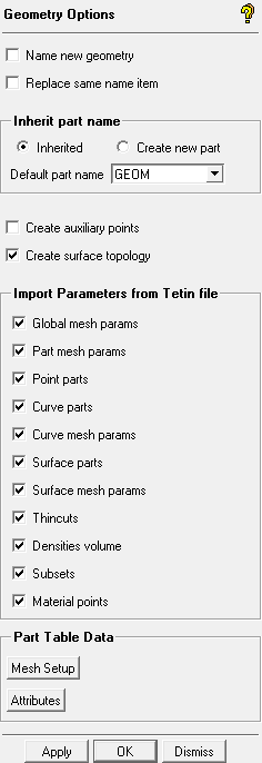
- Name new geometry
enables the display of entity names and modification of entity names when creating geometry entities. If disabled, the entity names will not be visible and the default naming convention will be followed.
Default Naming Convention
If the last two characters of an entity name are digits, then the numbers will be incremented for each new entity created. If the last two characters are not digits, then new entity names will be generated by adding "00" to the name and successively incrementing the number. Examples are shown below.
Entity name Next Entity Name (Automatically Generated) abc00 abc01 abc.53 abc.54 abc.1 abc.00 abc0.1 abc000 Note: Part names and entity names should be less than 64 alphanumeric characters. Names should start with a letter, not a digit. Evaluators ( +, -, /, and * ) should not be used in names because they can be misinterpreted as expressions or as denoting an assembly. Part names are written with all upper-case characters. Entity names are case sensitive.
- Replace same name item
enables replacing the previously existing entity when an existing name is used for an entity. If disabled, then the new entity will automatically be named according to the default naming convention and the next incremented name will appear in the Name field.
- Inherit part name
controls the default behavior of new geometry entities that are created.
Inherited
specifies that all applicable geometry operations will take the part name from the first object selected. This inherited part name will be used for the new objects that are created.
Create New
specifies that new geometry objects will be created in the working part name (the part name defined in the Point, Curve, Surface, Faceted Data, or Repair forms). Some operations, such as Create Point From Screen, requires a specified working part, so it will take on the working part name even if the Inherited option is used.
- Default Part Name
specifies the default working part for any new geometry created in Point, Curve, Surface, Faceted Data, or Repair forms. The working part name for a particular project can be changed independent of this default name.
- Create auxiliary points
retains the points used in the creation of geometry.
- Create surface topology
creates and maintains the topological connections when geometry is created.
Note: This is currently only used for Create/Modify Surface functions.
- Import Parameters from Tetin file
allows you to select which type of mesh parameter(s) to import with the model. By default, all mesh parameters are imported. ICEM CFD attempts to match parameters to the geometry by element name.
- Global mesh params
will change the global mesh parameters.
- Part mesh params
will change the part mesh parameters as selected under Import Model.
- Point parts
will change the part assignment and also import dormant points.
- Curve parts
will change the part assignment and also import dormant curves. Mesh parameters are unaffected.
- Curve mesh params
will change only the mesh parameters. Part assignments and dormancy are unaffected.
- Surface parts
will change only the part assignment.
- Surface mesh params
will change only the mesh parameters.
- Thincuts
will clear existing thincuts and import all thincuts from the tetin file.
- Densities volume
will clear existing densities and import all densities from the tetin file.
- Subsets
will clear existing subsets and import all subsets from the tetin file.
- Material points
imports bodies and material points.
Note: This option should be disabled if both and are enabled (under > ), which creates a new material point during model import.
- Part Table Data
These options apply to the Part Mesh Setup and Edit Attributes tables, with are accessed by right-clicking on the Parts Display Tree.
- Mesh Setup
opens the Mesh Setup Data dialog with the various options available for the Part Mesh Setup table. All options are enabled by default.
- Attributes
opens the Attributes Data dialog with the various options available for the Edit Attributes table. All options are enabled by default.