![]() The Ogrid Block option allows you to modify a single block or blocks to a 5 sub-block topology (7 sub-blocks in 3D) as shown below. It arranges grid lines into an "O" shape to reduce skew where a block corner lies on a continuous curve or surface. There are several variations of the basic Ogrid generation technique.
The Ogrid Block option allows you to modify a single block or blocks to a 5 sub-block topology (7 sub-blocks in 3D) as shown below. It arranges grid lines into an "O" shape to reduce skew where a block corner lies on a continuous curve or surface. There are several variations of the basic Ogrid generation technique.
The Ogrid can be created with or without face selection as shown in Figure 340: Ogrid Creation With and Without Face Selection.
Figure 340: Ogrid Creation With and Without Face Selection
a) Circular Cylinder |
b) Block Inside Cylinder |
c) Ogrid created without face selection |
d) Ogrid created with face selection  |
Ogrids can be created or removed by selecting or deselecting Blocks, Faces, Edges, and Vertices.
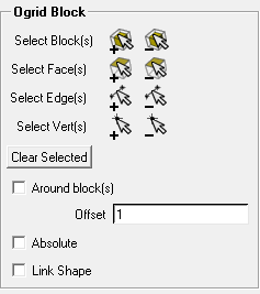
The following options are also available:
- Clear Selected
clears the previously selected entities.
- Around block(s)
enables the creation of the Ogrid extending outward from the selected block(s) surfaces.
- Offset
specifies the height of the Ogrid layer.
- Absolute
when enabled, the value assigned for Offset is the actual length of the radial edge of an Ogrid. Assigning a Offset of 7 would make all the radial edges of the Ogrid 7 units in length.
When Absolute is disabled, Offset behaves like a relative distance: A value of 1 causes the Hexa Mesher to place the Ogrid at a location where the resulting blocks will be distorted the least. A higher value makes the inner blocks of the Ogrid smaller, with the surrounding blocks larger, and a smaller value makes the inner blocks larger and the surrounding blocks smaller.
- Link Shape
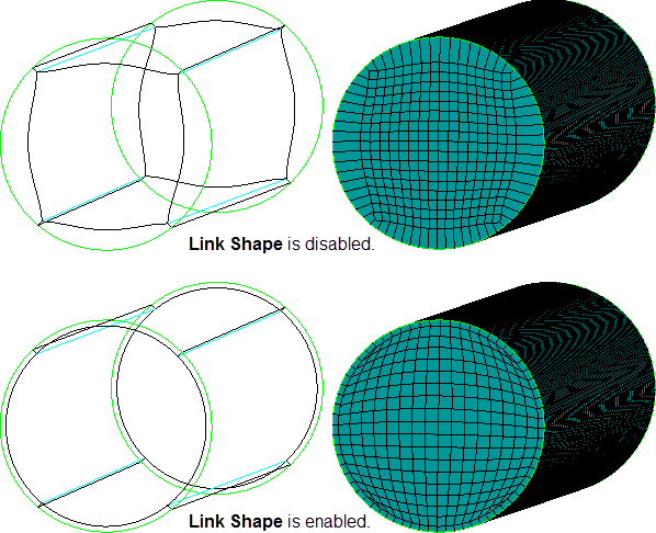
when enabled, the internal Ogrid block will be created with all internal edges and faces shaped by the nearest, corresponding geometry. This can help create a more exact offset of the internal edges/faces, and help maintain more uniform grid heights in the OGrid region. However, edges and blocks internal to the OGrid may not be able to smooth away as quickly thereby affecting the mesh in those regions. That is, if enabled, the mesh quality in the OGrid regions should improve while the mesh in the internal blocks could get worse, and the overall mesh quality may suffer.
In Figure 342: Link Shape Example, an Ogrid split in a simple cylinder is shown with Projected mesh shape enabled. The Ogrid in the upper images was created with Link Shape disabled. In the lower images, Link Shape was enabled.