Splits a free block by constructing a single face or several faces from loops of selected edges.
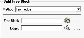
Select the blocking entities using the selection tools for Free Block and Edges. The resulting split depends on the blocking topology and edge loop selection.
Note: The split needs to fully separate the block. Hanging faces (baffle face that don't fully split the block) are not supported.
- Nested loops
All edges are chosen in one pass even if the selection contains multiple loops. The edges should be near planar as a single face is constructed from the selection, creating the split.
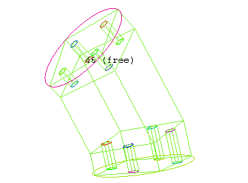
The example shown illustrates how the split face includes the selected, planar edges. In Figure 352: Single Free Block with Holes, the initial 3D multizone blocking has been created and Split Block was used to position edge splits aligned with the holes.
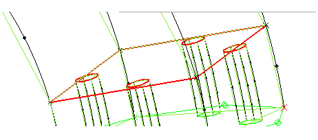
Figure 353: Nested Edge Loops Selected shows the selection of edges necessary to split the free block.
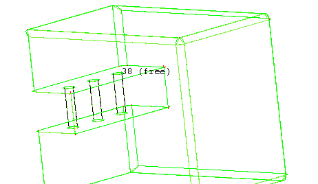
The split is completed as shown in Figure 354: New Free Block Created. The original free block has been blanked to better illustrate the new free block.
- Separated Loops
Selection of edges may contain multiple loops and may be chosen in multiple passes. Individual loops are found from the selection and used to create one sheet per loop. The block is split at these sheets.
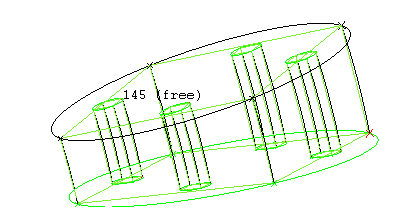
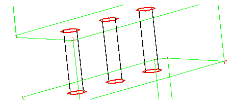
The example shown illustrates how the split sheets are created individually at the edge loops. In Figure 355: Single Free Block showing Connecting Tubes, the initial 3D multizone blocking has been created.
Figure 356: Individual Edge Loops Selected shows the selection of edges necessary to split the free block.
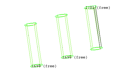
The split is completed as shown in Figure 357: New Free Blocks Created. The original free block has been blanked to better illustrate the new free blocks.
You can see how one free block can be separated into multiple free blocks in one operation. This approach is helpful for cases such as this perforated plate example.