


A common operation that you will perform with the Materials panel is the modification of an existing material. Items in the Materials library, themselves, cannot be edited. Instead, you can create a copy of an existing material for use in your model and then edit the copy.
The steps for this procedure are as follows:
Expand the node for the type of the material (for example, Fluid, Solid, Surface) in the Project tab of the Model manager window. Expand the node for the sub-type of the material (for example, Immersion fluids in Figure 9.50: The Materials Node in the Library Tab of the Model manager Window) and select the material item under the sub-type node. Right-click on the material item and select Edit in the drop-down menu to open the Materials panel. You can also open the Materials panel by selecting the material item in the Project tab of the Model manager window and clicking on the
 button in the Object
modification toolbar. Figure 9.51: The Materials Panel for a Solid Material (Properties Tab) shows
the Materials panel for a solid material.
button in the Object
modification toolbar. Figure 9.51: The Materials Panel for a Solid Material (Properties Tab) shows
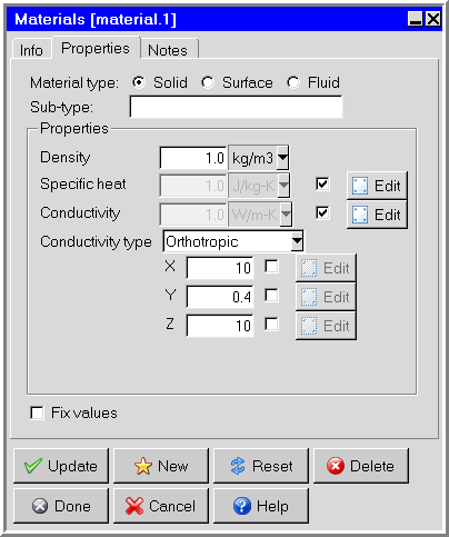
the Materials panel for a solid material. The Material type and the Sub-type for the material will be displayed in the Properties tab of the Materials panel. The lower part of the panel will change depending on your selection of material type.
Change the name of the material, if required. The name of the currently selected material is displayed in the Name text entry box in the Info tab of the Materials panel. You can change the name of the material by entering a new name in the Name text entry field.
Alternatively, you can rename a material using the Model manager window. Right-click the material item and select Rename in the drop-down menu. In the subsequent Rename object dialog box, enter a new name in the text entry field and click Done.
In the Properties tab, specify whether you want to fix the values for the units in the panel. See The Fix values Option for details.
Define the properties of the material. The properties for different types of materials are described below.
Click Update to save the changes to the material for the current project and keep the Materials panel open, or click Done to save the changes to the material for the current project and close the Materials panel.
You can also edit the definition of a material in any panel that contains a materials list. For example, the Walls panel contains a list called the External material list. To edit the properties of the material selected in the External material list, open the list and select Edit definition. This will open the Materials panel and display the properties of the selected material. You can edit the definition of the material as described above. Click Done when you have finished editing the material, and Ansys Icepak will close the Materials panel and return to the Walls panel.
Note: Any changes you make to the materials in the current project will be saved as part of the current project only. These changes will be available whenever you work on this project, but not for any other project. See Saving Materials and Properties for details on saving material properties to a library.
Editing a Solid Material
The inputs for editing a solid material are shown in Figure 9.51: The Materials Panel for a Solid Material (Properties Tab). The following properties are defined for solid materials:
Specific heat is the specific heat capacity of the solid. To define specific heat enable the check box next to the input box and click the adjacent Edit button. This will open the Solid specific heat panel. For details, refer to Defining Properties Using Temperature-Dependent Functions.
Conductivity is the thermal conductivity of the solid. To define conductivity enable the check box next to the input box and click the adjacent Edit button. This will open the Solid conductivity panel. For details, refer to Defining Properties Using Temperature-Dependent Functions.
Conductivity type contains a list of options for specifying the thermal conductivity. To specify an isotropic conductivity, select Isotropic from the Conductivity type drop-down list and enter a value for the Conductivity. You can specify a non-isotropic conductivity in Ansys Icepak, where the thermal conductivity varies with respect to one or more coordinate axes. There are four non-isotropic conductivity options available in Ansys Icepak:
To define an orthotropic thermal conductivity, select Orthotropic from the Conductivity type drop-down list and specify the thermal Conductivity. To define the degree to which the orthotropic conductivity varies in each coordinate direction, specify a scaling factor for the conductivity in each of the X, Y, and Z coordinate directions. The solid conductivity for each coordinate direction can be defined as a temperature-dependent function by enabling the check box next to the input box and clicking the adjacent Edit button. For details refer to Defining Properties Using Temperature-Dependent Functions.
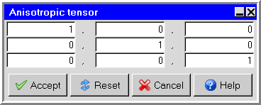
To specify an anisotropic thermal conductivity, specify the thermal Conductivity and then select Anisotropic from the Conductivity type drop-down list. To define the degree to which the anisotropic conductivity varies in each direction, specify a scaling factor for the conductivity in each of the XX, XY, XZ, YX, YY, YZ, ZX, ZY, and ZZ directions, respectively, next to Tensor. Alternatively, you can click the Edit button to the right of the Tensor text entry field. This opens the Anisotropic tensor panel (Figure 9.52: The Anisotropic tensor Panel).
Enter the scaling factors for the conductivity in the following way in the Anisotropic tensor panel:

(9–1)
To specify a biaxial thermal conductivity, select Biaxial from the Conductivity type drop-down list and specify the thermal Conductivity. To define the degree to which the biaxial conductivity varies in each direction, specify a scaling factor for the conductivity in the Normal and In-plane directions.
To specify a cylindrical orthotropic conductivity, select Cyl-Orthotropic from the Conductivity type drop-down list. To define the degree to which the cylindrical orthotropic varies in direction, specify a scaling factor for the conductivity in each direction. Enter values for z (axial), r (radial), and Θ (tangential). Click on Origin and Axis to set and be referenced by all objects. To change the global coordinate information, click the Edit button next to Origin or Axis. When Origin or Axis is not enabled, Icepak automatically uses coordinate information from corresponding objects.
The thermal conductivity is used when temperature is included in the problem (see Solution Variables). When modeling a transient problem, density and specific heat will also be used. See Transient Simulations for details on transient simulations.
Editing a Fluid Material
Note: When editing a fluid materials' Name, do not begin the name with an underscore and include a hyphen. If a fluid material is named, for example, _fluid-material an error occurs during the solution process.
The inputs for editing a fluid material are shown in Figure 9.53: The Materials Panel for a Fluid Material.
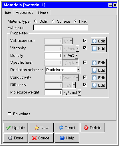
The following properties are defined for fluid materials:
Vol. expansion is the volumetric expansion coefficient of the fluid.
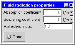
Radiation behavior specifies whether the material is Opaque or will Participate in the radiation calculation when assigned to an object. When Participate is selected, click Edit to open the Solid radiation properties panel and specify the Asborption coefficient, Scattering coefficient, and Refractive index. Asborption coefficient and Scattering coefficient specify the change in radiation intensity per unit length along the path through the material. Refractive index specifies the ratio of speed of light in the material to the speed of light in vacuum.
Conductivity is the thermal conductivity of the fluid (which can be velocity- or temperature-dependent).
Diffusivity is the mass diffusivity of the fluid used in the species transport equations.
The density and viscosity of the fluid are used in all flow
problems, but Ansys Icepak automatically sets an effective viscosity
when the flow is turbulent, as described in Flow Regime. The thermal conductivity and specific
heat are used when temperature is included in the problem (see Flow, Temperature
and Species Variables). Again, Ansys Icepak automatically
sets an effective conductivity when the flow is turbulent. The volumetric
expansion coefficient of the fluid is used when natural convection
due to gravity effects is present (see Forced- or Natural-Convection Effects). If gravity is not
activated, the volumetric expansion coefficient is not used. By default, Ansys Icepak uses the Boussinesq approximation (see The Boussinesq Model) to model the buoyancy force
and in this case Ansys Icepak uses a constant density in its calculations.
If you select the ideal gas law to model the buoyancy force, Ansys Icepak uses a density that varies as  as described in Incompressible Ideal Gas Law.
Note: If you use the ideal gas law and you have created a new fluid material, make sure that you specify the correct molecular weight for the new material.
Editing a Surface Material
The inputs for editing a surface material are shown in Figure 9.55: The Materials Panel for a Surface Material.
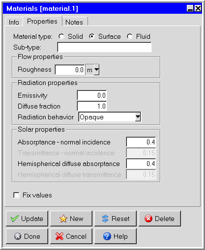
The following properties are defined for surface materials:
Flow properties
Radiation properties
Diffuse fraction is the fraction of reflected radiation flux that is to be treated as diffuse. The default setting is 1, indicating that all of the radiation is diffuse. A diffuse fraction equal to 0 indicates purely spectral reflected radiation. A diffuse fraction between 0 and 1 indicates partially diffuse and partially specular reflected energy.
Radiation behavior specifies the solar classification of a material. Opaque and Semi-transparent are the two available options.
Solar properties
Absorptance-normal incidence is the fraction of direct solar irradiation energy that is absorbed by the semi-transparent surface for a direct solar irradiation beam normal to the surface.
Transmittance-normal incidence is the fraction of direct solar irradiation energy that passes through the semi-transparent surface for a direct solar irradiation beam normal to the surface.
Hemispherical diffuse absorptance is the fraction of diffuse solar irradiation energy that is absorbed by the semi-transparent surface.
Hemispherical diffuse transmittance is the fraction of diffuse solar irradiation energy that passes through the semi-transparent surface.
The roughness of the surface is used when the flow is turbulent, as described in Flow Regime. The emissivity is used when radiation is modeled (see Radiation Modeling). Solar and diffuse absorptance and transmittance properties are used when solar loading is modeled (see Modeling Solar Radiation Effects). Properties of semi-transparent surface radiation account for its solar performance relative to direct solar irradiation and diffuse solar irradiation. One semi-transparent surface material may be used to represent the lumped effect of fenestration containing several glazing layers. For any semi-transparent surface, the sum of absorptance, transmittance, and reflectance must equal 1 for each type of solar irradiation. Therefore, it is sufficient to specify only two of the three solar performance properties for each type of radiation.