


To include a grille in your Ansys Icepak model, click the  button in the Object
creation toolbar and then click the
button in the Object
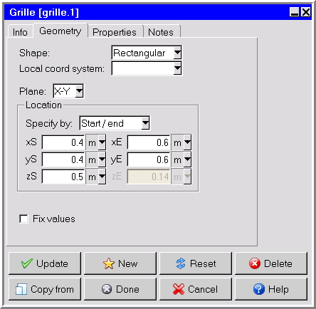
creation toolbar and then click the  button to open the Grille panel, shown in Figure 13.4: The Grille Panel (Geometry Tab) and Figure 13.5: The Grille Panel (Properties Tab).
The procedure for adding a grille to your Ansys Icepak model is as follows:
Create a grille. See Creating a New Object for details on creating a new object and Copying an Object for details on copying an existing object.
Change the description of the grille, if required. See Description for details.
Change the graphical style of the grille, if required. See Graphical Style for details.
In the Geometry tab, specify the geometry, position, and size of the grille. There are five different kinds of geometry available for grilles in the Shape drop-down list. The inputs for these geometries are described in Geometry. See Resizing an Object for details on resizing an object and Repositioning an Object for details on repositioning an object.
Note: The decoration shown on the grille object in the graphic display window is not displayed when the grille is a CAD object.
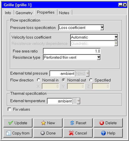
In the Properties tab, specify the characteristics for the grille.
Select the Pressure loss specification in the drop-down list. The following options are available:
To specify the loss coefficient, select Loss coefficient and then select the method to be used to calculate the velocity loss coefficient. The following options are available in the Velocity loss coefficient drop-down list.
To have Ansys Icepak calculate the loss coefficient for a particular grille type based on the free area ratio of the grille, select Automatic. Then select the type of grille (Perforated thin vent, Circular metal wire screen, or Two-plane screen, cyl. bars) in the Resistance type drop-down list and specify the Free area ratio.
To use the device-velocity method, select Device and select the method to be used to calculate the Resistance velocity dependence. There are three options in the drop-down list: Linear, Quadratic, and Linear+quadratic. Finally, specify the appropriate Loss coefficient and Free area ratio for the Linear coefficient and/or Quadratic coefficient.
To use the approach-velocity method, select Approach and select the method to be used to calculate the Resistance velocity dependence. Finally, specify the appropriate Loss coefficient for the Linear coefficient and/or Quadratic coefficient.
Note: When grilles are placed on domain boundaries, only quadratic loss coefficients should be specified. If linear loss coefficients are specified for such grilles, they will be ignored.
To define a piecewise-linear profile for the pressure drop as a function of the speed of the fluid through the grille, select Loss curve. Ansys Icepak allows you to describe the curve either by positioning a series of points on a graph using the Pressure drop curve graphics display and control window (described below), or by specifying a list of grille speed/pressure coordinate pairs using the Curve specification panel (described below). These options are available under Edit.
Note: You must define three points to create the curve by creating three points on the Pressure drop curve panel or specifying three coordinate pairs in the Curve specification panel.
To load a previously defined curve, click Load. This will open the Load curve file selection dialog box. Select the file containing the curve data and click Accept. See File Selection Dialog Boxes for details on selecting a file.
To save a curve, click . This will open the Save curve dialog box, in which you can specify the filename and directory to which the curve data is to be saved.
Note: The box to the right of Edit will be empty if you have not defined a curve for the grille. This box will contain the first speed value if you have defined a curve.
To specify the external pressure, enter a value for the External total pressure. For flow into a grille, the external pressure is the stagnation pressure. For flow out of a grille, the external pressure is the static pressure. By default, the external pressure is the ambient pressure specified under Ambient conditions in the Basic parameters panel (see Ambient Values).
Specify the Flow direction. There are three options:
If the fluid flows into the cabinet normal to the grille, select Normal in.
If the fluid flows out of the cabinet normal to the grille, select Normal out.
To specify the flow angle of the fluid entering the cabinet through the grille, select Specified. Enter values for the direction vector (X, Y, Z) for the flow. Only the direction of the vector is used by Ansys Icepak; the magnitude is ignored.
Specify the inlet or outlet species concentrations for the grille, if required. You can input the species concentrations for the grille using the Species concentrations panel. To open this panel, select Species in the Grilles panel and then click Edit. See Species Transport Modeling for details on modeling species transport.
Enter a value for the External temperature of the external fluid. The default value of Ambient temperature is the ambient temperature specified under Ambient conditions in the Basic parameters panel (see Ambient Values). This temperature is used if fluid flows into the cabinet through the vent, and is ignored if fluid flows out of the cabinet through the vent.