


Edit the link parameters in the Link panel (Figure 10.14: Example of a Link Panel).
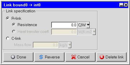
In the Link panel, select R- link and specify
the thermal Resistance or select C- link and
specify the Mass flow. The thermal resistance for links connecting face
nodes and internal nodes can be specified either by choosing Resistance
or Heat transfer coeff.. For links between two internal nodes, only the
Resistance option can be used. If Heat transfer
coeff. is specified, Ansys Icepak computes the thermal resistance as
 where h is the heat transfer coefficient and
A is the area of the face. If you have selected Mass
flow and want to reverse the direction of the flow, click
Reverse. Click Done to display the link in the
working area.
where h is the heat transfer coefficient and
A is the area of the face. If you have selected Mass
flow and want to reverse the direction of the flow, click
Reverse. Click Done to display the link in the
working area.
The link will be displayed by connecting the two nodes with a zig-zagged line. If the link is specified by a mass flow rate, an arrow will be displayed to indicate the direction of the flow. To edit an existing link, double-click the link in the Network editor panel.