


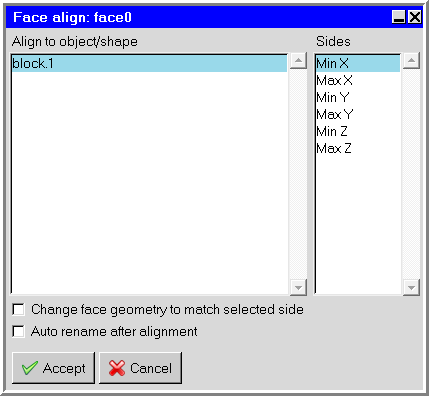
If you need to specify the geometry of newly-created faces, navigate to Geometry tab and then double-click the face node in the working area of the Network editor. The face node's tab is automatically selected. Specify the geometry, position and size of the new face. Or you can press Shift and right-click on a face node in the network editor to display the context menu. Select Align to to open the Face align panel. Select the side of an object or shape to align the face node to. You can select Change face geometry to match selected side to ensure the face node geometry matches that of the selected side. Also, if you enable Auto rename after alignment, the face node name will be renamed to the selected "align to" object and side. For example, if the face was aligned to the "Min X" face of object "Block01," the face node name after alignment will become "Block01:Min X."
Edit the node parameters in the Node panel. Figure 10.11: Example of a Node Panel (Face Node)-Figure 10.13: Example of a Node Panel (Internal Node) show examples of Node panels specific to each type of node. To open a Node panel, double-click the node in the working area of the Network editor panel.
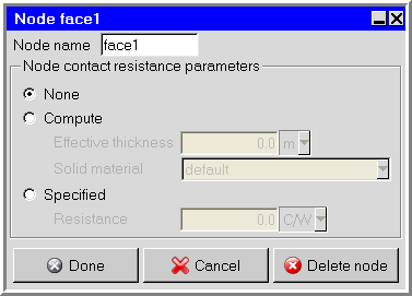
For a face node, specify the name of the node in the Node name text entry box, and then specify whether or not a contact resistance is applied to the face.
If there is no contact resistance, select None.
If you would like Ansys Icepak to calculate a contact resistance based on the properties of the face, select Compute and specify the Effective thickness of the network node and the Solid material of which it is made. The values of the effective thickness and the thermal conductivity of the solid material will be used to calculate the contact resistance of the network node.
If you want to specify the contact resistance yourself, select Specified and enter a Resistance in the text-entry field.
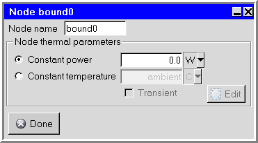
For a boundary node, specify the name of the node in the Node name text entry box. Select Constant power or Constant temperature as the boundary condition and specify a value for the parameter.

For an internal node, specify the name of the node in the Node name text entry box, and then specify values for the Power, Mass, and Specific heat of the node.
For transient simulations, you can also specify transient power parameters for an internal node or transient temperature parameters for a boundary node. To edit the transient power or temperature parameters for the network, turn on the Transient option and click the adjacent Edit button. This option is available if you have selected Transient under Time variation in the Basic parameters panel. See Transient Simulations for more details on transient simulations.
Note:
You can view Node settings by pointing the mouse at the node and the settings will be displayed as a bubble help window.
You can also view Node and Power values in the Networks tab of the Power and temperature limit setup panel. See Setting Up the Power and Temperature Limit Values for more details.