


The default configuration shows one view of your model in the main Graphics window. This initial viewport, which covers the Graphics window cannot be removed and is always used to clear (erase) the Graphics window prior to a redraw. You can create up to fifteen viewports that will overlay the Graphics window. These viewports can be interactively resized and relocated within the Graphics window using the mouse and the visibility of each can be controlled on a per viewport basis. Transformations, and Z-clip location settings can also be made independently in each viewport. When in viewport mode, you are always modifying the viewports selected in the Graphics window. Selected viewports are outlined with translate and scale transformation actions, while unselected objects are outlined in a black color. Multiple viewports are helpful in showing the same object from multiple views, showing different axes in each viewport, showing the same objects with different attributes, etc. The maximum number of viewports is 15.
To create a new viewport, right-click Viewports in the Outline View tree and select New....
![]() Display Settings
→ Viewports
Display Settings
→ Viewports
![]() New...
New...
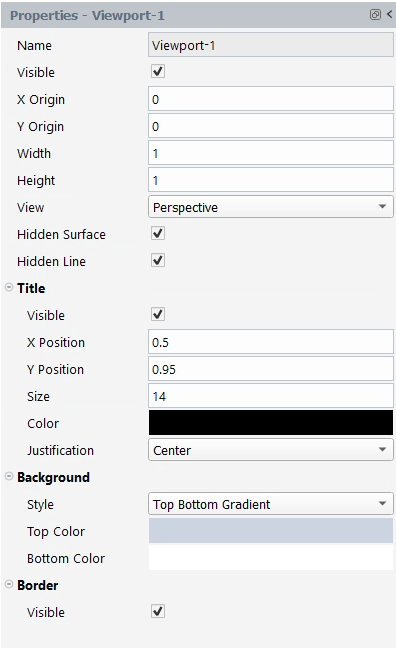
The following options are available when creating viewports:
Name
(Optional) Enter a name for the viewport.
Visible
Select to hide or unhide the viewport.
X Origin
Specify the location for the x-coordinate of the selected viewport's origin (lower left corner) in the main Graphics window. Values range from 0.0 to 1.0.
Y Origin
Specify the location for the y-coordinate of the selected viewport's Origin (lower left corner) in the main Graphics window. Values range from 0.0 to 1.0.
Width
Specify the width of a selected viewport in X and Y coordinates from the viewport's Origin. Values range from 0.0 to 1.0.
Height
Specify the Height of a selected viewport in X and Y coordinates from the viewport's Origin. Values range from 0.0 to 1.0.
View
Specify the view of global settings for Perspective versus Orthographic display, hidden surface display, and hidden line display applied in the selected viewport(s). In addition, a viewport can be designated as 2D, in which case only planar 2D parts can be displayed in the viewport.
Title
Set title specific options:
Visible
Select to hide or unhide the viewport title.
X Position
Specify the x-position of the viewport title.
Y Position
Specify the y-position of the viewport title.
Size
Specify the size of the viewport title.
Color
Specify the color of the viewport title.
Justification
Choose , or justification for the viewport title.
Background
Set background specific options:
Style
Choose coloring styles for your viewport.
Top Color
Select to specify a background color for the top half of the viewport.
Bottom Color
Select to specify a background color for the bottom half of the viewport.
Border
Set border specific options:
Visible
Select to hide the viewport border.
Click Delete at the bottom of the viewport properties to delete an viewport.
Viewport Linking
![]() Display Settings
→ Viewports
Display Settings
→ Viewports ![]() Link
Viewports...
Link
Viewports...
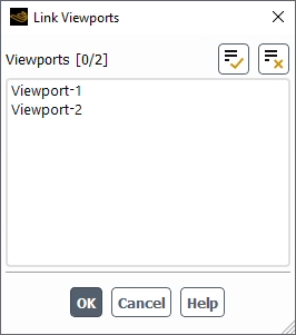
The Link Viewports dialog enables you to link the selected viewports together allowing the same transformation (for example, translate, scale) to be applied to all linked viewports.