Case Comparison can be used to analyze results between two identical or different datasets using a specific viewport layout.
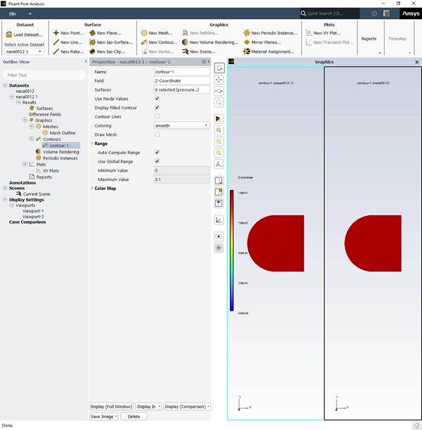
When multiple datasets are read into Post-Analysis, a Case Comparison node appears in the Outline View. Additionally, a button becomes visible within the properties panel of Graphics objects (Mesh Outline, Contours, Volume Rendering, etc...). The settings within the Properties - Case Comparison panel allow you to define the datasets and layout orientation to use for the comparison. These layouts are automatically linked and adjusting the view of first viewport will adjust the view of the second.
Note: When creating a case comparison, any missing objects are automatically created in other datasets.
To create a new case comparison, select Case Comparison in the Outline View tree.
![]() Case Comparison
Case Comparison
The following options are available when creating a global scene:
Active
Select to activate the case comparison.
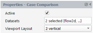
Datasets
Select the datasets to use for the case comparison.
Viewport Layout
Choose the layout orientation for the case comparison.
Once you have made changes to your property settings, click , within a Graphics object properties panel, to visualize the objects in the Graphics window.
Note: The currently active viewport will have a cyan border.
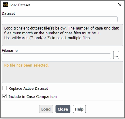
When loading two datasets into Post-Analysis, an checkbox appears when is disabled. Enabling this checkbox activates the Difference Fields and Case Comparison nodes which appears in the Outline View.
To create a difference field, right-click Difference Fields in the Outline View tree and select New....
![]() Results → Difference
Fields
Results → Difference
Fields ![]() New...
New...
The Properties - Difference Fields panel allows you to create a new difference field object.
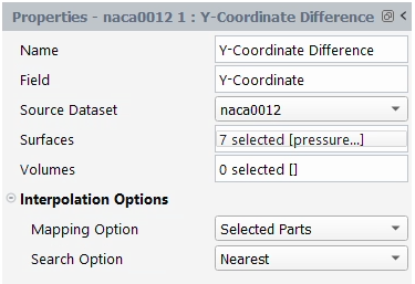
The following options are available when creating difference fields:
Name
(Optional) Enter a name for the mesh object.
Field
Select the field variable to be used in the difference.
Source Dataset
Choose the dataset with which the difference will be computed.
Surfaces
List of surfaces where the difference field will be created.
Volumes
List of volumes where the difference field will be created.
Interpolation Options
Set the interpolation options for the field:
Mapping Option
Choose how the node under Source Dataset, used for the comparison, will be found.
The node will be searched globally. (Can be computationally expensive)
The node will be searched in parts of same dimensionality.
The node will be searched only on the selected parts.
Search Option
Choose how the node under Source Dataset, used for the comparison, will be searched.
Considers only nodes that are coincident with nodes in the target dataset.
Considers the nearest node.
Difference Fields can also be applied to
Contour or Volume Rendering objects by
selecting the or commands, ![]() Contours
→ contour-1
Contours
→ contour-1 ![]() Display
(Comparison) → Difference/, a Difference Fields
node is then automatically created in the Outline View
Display
(Comparison) → Difference/, a Difference Fields
node is then automatically created in the Outline View
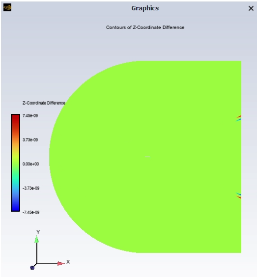
When applied, the object uses the following naming format, current object name + -difference(dataset name). The Contour or Volume Rendering object difference is also displayed in the Graphics window.
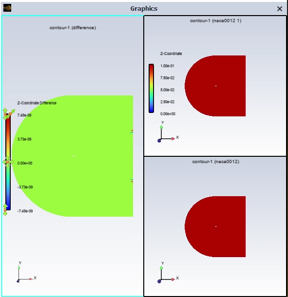
If is selected,
![]() Contours → contour-1
Contours → contour-1
![]() Display (Comparison)
→ Case Comparison with Difference, a 3 viewport
layout is applied, and the difference is shown in the first viewport, and comparison
objects are shown in the other two viewports.
Display (Comparison)
→ Case Comparison with Difference, a 3 viewport
layout is applied, and the difference is shown in the first viewport, and comparison
objects are shown in the other two viewports.