


Once beta feature access is enabled, you can use the following additional evaporation-condensation models to simulate mass transfer in VOF or mixture multiphase problems:
Hertz-Knudsen model in pressure form
Hertz-Knudsen model in temperature form
Interfacial heat flux model
This section contains information about the following models:
In the Hertz-Knudsen model, the interfacial mass transfer is derived based on the kinetic theory of gases [1].
Hertz-Knudsen Model in Pressure Form
The rate of mass transfer due to evaporation and condensation in the pressure form is described as:
 | (15–3) |
where
 = model constant for evaporation/condensation = model constant for evaporation/condensation |
 = interfacial area density = interfacial area density |
 = molecular weight = molecular weight |
 = universal gas constant = universal gas constant |
 = saturation temperature = saturation temperature |
 and and  = saturation pressure and partial pressure of the vapor
phase, respectively = saturation pressure and partial pressure of the vapor
phase, respectively |
Vapor partial pressure  is defined as:
 | (15–4) |
where  is system pressure, and
  is the mole fraction of vapor.
The mass transfer rate due to evaporation and condensation can be converted to the relative humidity form expressed as:
 | (15–5) |
where  is the relative humidity defined as:
 | (15–6) |
Hertz-Knudsen Model in Temperature Form
Using the Clausius-Clapeyron equation
 | (15–7) |
the pressure form of the mass transfer rate Equation 15–3 can be converted to the temperature form:
 | (15–8) |
where  is the latent heat, and
  and
and  are the vapor and liquid densities, respectively.
Wall Evaporation/Condensation Model
The mass transfer rate at the wall  ̇ is specified as:


In the above equations,  is the wall area density.
Area Density
The gradient-based interfacial area density (ia-gradient for the VOF and mixture multiphase models) is calculated as:
 | (15–11) |
Symmetric interfacial area density (ia-symmetric for the mixture multiphase model only) is calculated as:
 | (15–12) |
where  and
and  are the volume fractions of liquid and vapor,
respectively
are the volume fractions of liquid and vapor,
respectively
Wall area density for the wall evaporation/condensation model is calculated as:
 | (15–13) |
where
 = wall area density = wall area density |
 = wall face area = wall face area |
 = volume of the neighboring cell adjacent to the
wall = volume of the neighboring cell adjacent to the
wall |
The effective mass transfer rate is estimated as:
 | (15–14) |
where  is a scaling factor.
In the interfacial heat flux model [2], the interfacial mass transfer is obtained by balancing conductive heat fluxes across the interface. The rate of mass transfer due to evaporation and condensation is described as:
 | (15–15) |
where
 and and  = thermal conductivities of liquid and vapor,
respectively = thermal conductivities of liquid and vapor,
respectively |
|
and = volume fractions of liquid and vapor,
respectively |
 = volume fraction gradient for liquid = volume fraction gradient for liquid |
 = temperature gradient = temperature gradient |
 and and  = multipliers with the default value of 1 = multipliers with the default value of 1 |
When including the evaporation/condensation mass transfer effects in a VOF or mixture multiphase simulation, in addition to the existing options, the following models are available in the Evaporation/Condensation Model group box of the Evaporation-Condensation dialog box (see Figure 15.1: The Evaporation-Condensation Model Dialog Box):
Hertz-Knudsen (Temperature)
Hertz-Knudsen (Pressure)
Interfacial Heat Flux
See Theory for more information about these models.
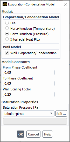
For the Hertz-Knudsen (Temperature) and Hertz-Knudsen (Pressure) models, you need to specify the following settings:
Specify the From Phase Coefficient and To Phase Coefficient model constants (
in Equation 15–3 and Equation 15–8 for the Hertz-Knudsen model, and
and in Equation 15–15 for the
Interfacial Heat Flux model).(if applicable) Select the Wall Evaporation/Condensation option and specify Wall Scaling Factor in the Model Constants group box (
 in Equation 15–14).
Specify Saturation Temperature (Hertz-Knudsen (Temperature) model) or Saturation Pressure (Hertz-Knudsen (Pressure) model).
See section "Evaporation-Condensation Mechanism" in the Ansys Fluent User's Guide and Evaporation-Condensation Binary Mass Transfer Mechanism for details about the available saturation property methods.
In the Interfacial Area tab, select the Interface Area density method.
For the Interfacial Heat Flux model, you need to specify Saturation Temperature. Model constants in most of the cases do not require any adjustment.
To control or improve the solution process, you can set the mass transfer
limiters by using the text commands available in the
solve/set/multiphase-numerics/heat-mass-transfer/evaporation-condensation/
menu.
To limit the mass transfer rate
use the following TUI command to set the minimum threshold of normalized area density:
solve/set/multiphase-numerics/heat-mass-transfer/evaporation-condensation/ia-norm-min-limitTo control the rate of evaporation for a given range of the volume fraction of the phase from which mass is transferred
use the following TUI commands:
To set the minimum limiter:
solve/set/multiphase-numerics/heat-mass-transfer/evaporation-condensation/vof-from-min-limitTo set the maximum limiter:
solve/set/multiphase-numerics/heat-mass-transfer/evaporation-condensation/vof-from-max-limit
To control the rate of condensation for a given range of the volume fraction of the phase to which mass is transferred
use the following TUI commands:
To set the minimum limiter:
solve/set/multiphase-numerics/heat-mass-transfer/evaporation-condensation/vof-to-min-limitTo set the maximum limiter:
solve/set/multiphase-numerics/heat-mass-transfer/evaporation-condensation/vof-to-max-limit
(Hertz-Knudsen (Pressure) model only) To control the rate of condensation, use the following TUI command to limit the maximum relative humidity value:
solve/set/multiphase-numerics/heat-mass-transfer/evaporation-condensation/max-rel-humidityThe default value for the maximum relative humidity is 2.


When one of the evaporation-condensation mass transfer models described in Setting up Evaporation/Condensation Mass Transfer is used, the following additional variable become available for postprocessing under the Phase Interaction... category:
- Bulk Mass Transfer Rate
is the evaporation-condensation mass transfer rate excluding the wall mass transfer rate.
- Interfacial Area Density
is the interfacial area per unit volume.
- Latent Heat
is the latent heat for the evaporation-condensation mass transfer mechanism. Note that plots with nonzero values will be generated only if the alternative energy treatment is used (see section "Alternative Modeling of Energy Sources" in the Ansys Fluent User's Guide); otherwise, the plots will display zero values everywhere inside the computational domain.
- Mass Transfer Rate
is the effective mass transfer rate.
- Saturation Temperature
is the saturation temperature of the evaporation-condensation mass transfer mechanism. Note that plots with nonzero values will be generated for all models except the Hertz-Knudsen (Pressure) model, in which case the plots will display zero values everywhere inside the computational domain.
- Vapor Pressure
is the pressure of the vapor phase. Note that plots with nonzero values will be generated only in case of the Hertz-Knudsen (Pressure) model; otherwise, the plots will display zero values everywhere inside the computational domain.
- Wall Mass Transfer Rate
is the evaporation-condensation mass transfer rate at the wall. Note that plots with nonzero values will be generated only if the Wall Evaporation/Condensation option is selected in the Evaporation/Condensation Model dialog box; otherwise, the plots will display zero values everywhere inside the computational domain.