


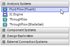
There are two basic types of systems: analysis systems and component systems. The following Fluent-based systems are available in Workbench:
The Fluid Flow (Fluent) analysis system enables you to perform a complete CFD analysis and contains cells that allow you to create geometry, generate a mesh, specify settings in Fluent, run the Fluent solver, and visualize the results in CFD-Post.
The Fluent component system enables you to access the Fluent application from within Workbench and contains only the cells needed to specify settings in Fluent and run the Fluent solver. When using a Fluent component system, a mesh must be imported into the system or provided through a connection from an upstream system.
The Fluent (with Fluent Meshing) component system enables you to generate a mesh, specify settings in Fluent, and run the Fluent solver. For this system, you can provide a geometry through the upstream connection and use a journal file to automatically generate a mesh for your application.
Note: A separate cell for results visualization is only needed when using CFD-Post. The postprocessing capabilities in Fluent can be accessed from both the Fluid Flow (Fluent) analysis system and the Fluent component system.
To create an analysis or component system in Workbench: In the Toolbox, double-clicking the desired system under Analysis Systems or Component Systems, respectively. Or you can click the system and drag it onto the Project Schematic. Notice that when you hover over systems in the Toolbox, a tool tip appears.
For more information, see the following sections:
The Fluid Flow (Fluent) analysis system is found in the Toolbox under Analysis Systems.
When you create the new Fluid Flow (Fluent) analysis system in Workbench (as described above), it appears in the Project Schematic as a box containing several cells (Figure 1.3: A Fluid Flow (Fluent) Analysis System). Each cell corresponds to a typical task you would perform to complete a CFD analysis.
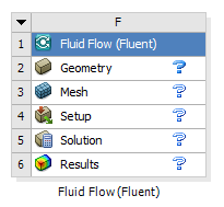
The following cells are available in a Fluid Flow (Fluent) analysis system:
- Geometry
allows you to define the geometrical constraints of your analysis. You can perform the following operations:
Import a pre-existing geometry into your system by using the context menu accessible through right-clicking the cell.
Create a new geometry either in Ansys SpaceClaim Direct Modeler (Windows only) or Ansys DesignModeler. The geometry editor is launched by either double-clicking the Geometry cell or right-clicking the cell and selecting an appropriate geometry option from the cell context menu. On Windows machines, the default geometry editor is SpaceClaim. You can change the preferred geometry editor to Ansys DesignModeler in the Options dialog box ( > > > > ).
Modify an existing geometry. Note that double-clicking a Geometry cell opens the geometry in the most recently used editor. You can also launch the editor of your choice by selecting the corresponding context menu option.
- Mesh
allows you to define and generate a computational mesh for your analysis. Double-clicking the Mesh cell opens Ansys Meshing and loads the current mesh database (or the geometry defined by the Geometry cell) if you have not yet begun working on the mesh. Alternatively, you can use the context menu (by right-clicking the Mesh cell) to import a pre-existing Fluent mesh into the system.
Important:Importing a Fluent mesh file into the Mesh cell results in the Mesh cell becoming the starting point for your analysis (and the name of the Mesh cell changes to Imported Mesh). Therefore, the Geometry cell (and data it contains) will be deleted from the system. The deleted Geometry cell can be retrieved by selecting Reset from the context menu of the Imported Mesh cell.
Fluent meshes imported into the Mesh cell cannot be modified by the Ansys Meshing application.
- Setup
allows you to define the boundary conditions, physical models and solver settings for the Fluent analysis. Double-clicking the Setup cell opens Fluent and loads the mesh defined by the Mesh cell as well as any Fluent settings that have already been specified. Alternatively, you can use the context menu (by right-clicking the Setup cell) to import a pre-existing Fluent case or mesh file into the system. After you specify the file you want to import, Fluent will open and load the file.
Important:If you open Fluent before defining a mesh, Fluent will open without loading any files. You can then choose to import files from the File ribbon tab in Fluent.
Importing a Fluent case or mesh file into the Setup cell or the Fluent application results in the Setup cell becoming the starting point for your analysis. Therefore, the Geometry and Mesh cells (and any data they contain) will be deleted from the system.
- Solution
allows you to calculate a solution in Fluent. Double-clicking the Solution cell opens Fluent and loads the current Fluent case and data files. If you have not yet performed any calculations, Fluent will load the mesh file as well as any settings that have been specified.
Important: You can also use the Solution cell context menu to import a pre-existing Fluent data file to use for initial solution data. If you have not yet performed any calculations, Fluent will load this data file in addition to the mesh and settings.
- Results
allows you to display and analyze the results of the CFD analysis. Double-clicking the Results cell opens CFD-Post and loads the current Fluent case and data files as well as the current CFD-Post state file.
Note: While it is possible to apply different names for the Setup or the Solution cells by right-clicking either cell, and selecting the Rename command in the context menu, it is not generally recommended to do so.
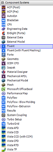
The Fluent and Fluent (with Fluent Meshing) component systems are found in the Toolbox under Component Systems.
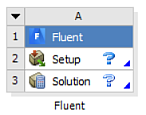
Fluent Component System
When you create a new Fluent component system in Workbench (as described above), it appears in the Project Schematic as a box containing two cells: Setup and Solution (Figure 1.5: A Fluent Component System).
The Setup and Solution cells in a Fluent component system work in the same manner as described above for the Fluid Flow (Fluent) analysis system (see Fluent-Based Analysis Systems). The only difference is that the mesh must originate from a file imported into the Setup cell or the Fluent application, or it must be provided through a connection from an upstream system.
Fluent (with Fluent Meshing) Component System
When you create a new Fluent (with Fluent Meshing) component system in Workbench, it appears in the Project Schematic as a box comprising three cells: Mesh, Setup, and Solution.
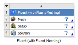
By double-clicking the Mesh cell, you can access Fluent Meshing, and define and generate a computational mesh for your problem. Upon opening, Fluent Meshing will automatically load either the current mesh data or, if the mesh data is not available, the geometry defined in the upstream Geometry cell. Otherwise, you can import input data file(s) directly into Fluent Meshing.
The Setup and Solution cells work in the same way as in the Fluid Flow (Fluent) analysis system (see Fluent-Based Analysis Systems).