


Geometry parameterization and exploration is available for exploring geometry designs for various design conditions, by means of mesh morphing. When design conditions are defined using input parameters, geometry parameterization and exploration can be used for a parametric study and for performing parametric analysis.
Geometry parameterization can be accessed by clicking in the Design ribbon tab ( Geometry group box).
![]() Design → Geometry
→
Design → Geometry
→
The graphical user interface (GUI) of the Parameterize and Explore dialog box is very similar to that of the Design Tool, but with more simplistic settings. While geometry parameterization is intended for exploring a design change based only on specified design conditions, the goal of the design tool is to compute the optimal freeform deformation using shape sensitivity and design constraints. Additionally, the adjoint solver is not required for geometry parameterization. Therefore only the design change, region, region conditions, design conditions, and numerics settings of the design tool are relevant for geometry parameterization.
Much of the procedure for geometry parameterization is the same as that of the design tool and therefore, much of the procedure below references sections in the design tool for defining the relevant settings. However, many settings described within Modifying the Geometry Using the Design Tool are not applicable to geometry parameterization.
The general workflow for performing geometry parameterization is as follows:
Define the morphing region by clicking the Region tab of the Parameterize and Explore dialog box.
Instruction on defining the morphing region within the design tool is the same for geometry parameterization, and is outlined in Defining the Region for the Design Change. Note that only the mesh inside the morphing region will be changed.
Define the region conditions by clicking the Region Conditions tab of the Parameterize and Explore dialog box.
Specify the region conditions for each coordinate direction:
You can ensure that the deformation is symmetrical relative to the different coordinate directions by enabling the Symmetric options. Symmetry can be imposed in as many directions as desired and when enabled, the symmetry planes will be displayed in the graphics window. You should ensure they reflect your intent for the design change, modifying the extents of the deformation region as necessary.
When the Symmetric option is enabled, the Custom Plane? option becomes available which, when enabled, allows you to enter a custom value for the plane of symmetry.
Periodic morphing can be enforced in the theta direction for cylindrical region conditions by entering the desired number of repeats under External Periodic. Note that periodic morphing is distinct from periodic boundary conditions and periodic repeats. For periodic morphing, when the desired number of repeats is
0or1, no repeats will be applied.Note: Symmetric and External Periodic conditions behave differently than the design tool's symmetric and periodic region conditions outlined in Defining Region Conditions.
The Apply Continuity option is enabled by default and is recommended to ensure that the nodes at the boundary of the region are fixed.
Define the design conditions by clicking the Design Conditions tab of the Parameterize and Explore dialog box.
Instruction on defining design conditions for geometry parameterization is the same as that of the design tool design tool and is outlined in Defining Conditions for the Deformation.
Create the desired design conditions for your parametric analysis, defining them as a constant value or defined using an input parameter. The following design conditions can be defined for geometry parameterization:
translation
scaling
rotation
prescribed-profile
compound
bounded-by-plane
bounded-by-surface (including fit to surface)
By default, all surfaces inside the morphing region (defined within the Region tab) may be modified unless specified by a design condition. Therefore it is important to define the fixed-walls constraint to fix any surfaces that should not be modified. Additionally, unlike the Design Tool where only the mesh inside the morphing region is morphed, for geometry parameterization, the mesh within a Symmetric or External Periodic region (defined within the Region Conditions tab) will also be morphed.
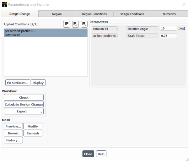
If you have defined a design condition with an input parameter, the parameter value will appear in the Parameters group box of the Design Change tab for easy modification and experimental trials. For example, if the Angle for a rotation condition is defined with an input parameter, the Rotation Angle parameter value will be shown in the Design Change tab.
(optional) Click the Numerics tab of the Parameterize and Explore dialog box.
Adjusting the numerics settings for the design change is optional and the settings generally do not need to be changed. However, numerics settings can be adjusted as follows:
Specify the value for the Constraints. This value is the absolute tolerance for convergence of the residuals associated with the design conditions, including fixed zone conditions in meters. Tighter tolerance may increase both the computational time and memory cost.
Increase Local Smoothness is disabled by default, and enabling it will use more local control points to improve the smoothness of the deformation.
Increase Global Smoothness is disabled by default, and enabling it will use more global control points to improve the smoothness of the deformation.
Calculate the design change and modify the mesh by clicking the Design Change tab of the Parameterize and Explore dialog box.
After creating one or multiple design conditions for your parametric analysis, they will become available in the Applied Conditions list of the Design Change tab.
Much of the procedure for calculating the design change and modifying the geometry within the Design Tool is the same for geometry parameterization, and is outlined in Shape Modification. However, some steps are not applicable for geometry parameterization, such as morphing and constraint methods and observable settings.