


This section contains methods for hooking UDFs to Ansys Fluent that
have been defined using DEFINE macros described
in Dynamic Mesh DEFINE Macros, and interpreted or
compiled using methods described in Interpreting UDFs or Compiling UDFs, respectively.
For more information, see the following sections:
After you have compiled (Compiling UDFs) your DEFINE_CG_MOTION UDF, the name of
the function you supplied as a DEFINE macro
argument will become visible and selectable in the Dynamic
Mesh Zones dialog box (Figure 6.114: The Dynamic Mesh Zones Dialog Box).
To hook the UDF to Ansys Fluent, you will first need to enable the Dynamic Mesh option in the Dynamic Mesh task page.
![]() Setup →
Setup → ![]() Dynamic Mesh →
Dynamic Mesh → ![]() Dynamic Mesh
Dynamic Mesh
Next, open the Dynamic Mesh Zones dialog box.
![]() Setup →
Setup → ![]() Dynamic Mesh → Create/Edit...
Dynamic Mesh → Create/Edit...
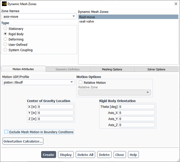
Select Rigid Body under Type in the Dynamic Mesh Zones dialog box (Figure 6.114: The Dynamic Mesh Zones Dialog Box) and click the Motion Attributes tab. Finally, select the function name (for example, piston::libudf) from the Motion UDF/Profile drop-down list, and click Create then Close.
See
DEFINE_CG_MOTION
for details
about DEFINE_CG_MOTION functions.
The DEFINE_DYNAMIC_ZONE_PROPERTY UDF
can be hooked in order to define the following:
the swirl center for in-cylinder applications
a variable cell layering height
After you have compiled your DEFINE_DYNAMIC_ZONE_PROPERTY UDF (as described in Compiling UDFs),
the name of the function you supplied as a DEFINE macro argument will become visible and selectable in the In-Cylinder Output Controls dialog box (Figure 6.115: In-Cylinder Output Controls Dialog Box).
To hook the UDF to Ansys Fluent, you must first right-click the General branch of the tree and select Transient from the Analysis Type sub-menu.
![]() Setup → General
Setup → General ![]() Analysis Type → Transient
Analysis Type → Transient
Next, enable the Dynamic Mesh option in the Dynamic Mesh task page.
![]() Setup →
Setup → ![]() Dynamic Mesh →
Dynamic Mesh → ![]() Dynamic Mesh
Dynamic Mesh
Then, enable the In-Cylinder option in the Options group box, and click the Settings button to open the Options dialog box. After you have updated the parameters in the In-Cylinder tab of this dialog box, click the Output Controls... button to open the In-Cylinder Output Controls dialog box (Figure 6.115: In-Cylinder Output Controls Dialog Box).
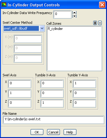
Select the UDF library (for example, swirl_udf::libudf) from the Swirl Center Method drop-down list in the In-Cylinder Output Controls dialog box. Click and close the In-Cylinder Output Controls dialog box.
See
DEFINE_DYNAMIC_ZONE_PROPERTY
for further
details about DEFINE_DYNAMIC_ZONE_PROPERTY functions.
After you have compiled your DEFINE_DYNAMIC_ZONE_PROPERTY UDF (as described in Compiling UDFs),
the name of the function you supplied as a DEFINE macro argument will become visible and selectable in the Dynamic Mesh Zones dialog box (Figure 6.116: The Dynamic Mesh Zones Dialog Box).
Important: Since the DEFINE_DYNAMIC_ZONE_PROPERTY UDF is a function of time or crank angle, you must make sure that
you have selected Transient from the Time list in the Solver group box
of the General task page before proceeding.
To hook the UDF to Ansys Fluent, you will first need to enable the Dynamic Mesh option in the Dynamic Mesh task page.
![]() Setup →
Setup → ![]() Dynamic Mesh →
Dynamic Mesh → ![]() Dynamic Mesh
Dynamic Mesh
Then, enable the Layering option in the Mesh Methods list, and click the Settings... button to open the Mesh Methods Settings dialog box. In the Layering tab, select Height Based from the Options list, and set the Split Factor and Collapse Factor to appropriate values. Then click .
Next, specify the meshing options in the Dynamic Mesh Zones dialog box (Figure 6.116: The Dynamic Mesh Zones Dialog Box).
![]() Setup →
Setup → ![]() Dynamic Mesh → Create/Edit...
Dynamic Mesh → Create/Edit...
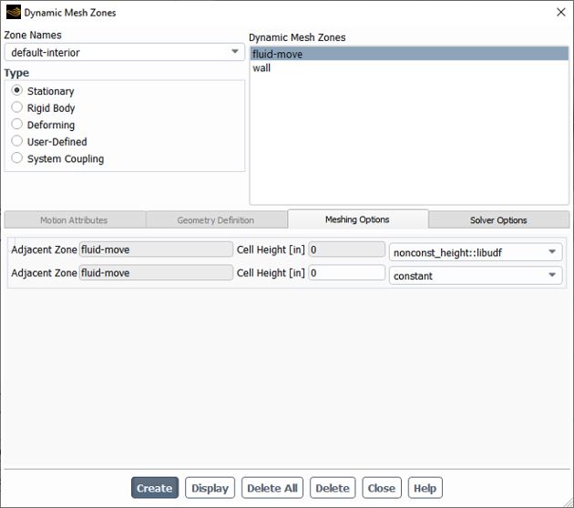
Select Stationary, Rigid Body, or User-Defined from the Type list in the Dynamic Mesh Zones dialog box. Click the Meshing Options tab, and select the UDF library (for example, nonconst_height::libudf) from the Cell Height drop-down list. Finally, click Create and close the Dynamic Mesh Zones dialog box.
See
DEFINE_DYNAMIC_ZONE_PROPERTY
for further
details about DEFINE_DYNAMIC_ZONE_PROPERTY functions.
After you have compiled (Compiling UDFs) your DEFINE_GEOM UDF, the name of the
function you supplied as a DEFINE macro argument
will become visible and selectable in the Dynamic Mesh Zones dialog box.
To hook the UDF to Ansys Fluent, you will first need to enable the Dynamic Mesh option in the Dynamic Mesh task page.
![]() Setup →
Setup → ![]() Dynamic Mesh →
Dynamic Mesh → ![]() Dynamic Mesh
Dynamic Mesh
Next, open the Dynamic Mesh Zones dialog box (Figure 6.117: The Dynamic Mesh Zones Dialog Box).
![]() Setup →
Setup → ![]() Dynamic Mesh → Create/Edit...
Dynamic Mesh → Create/Edit...
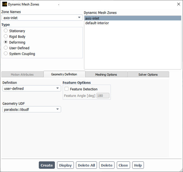
Select Deforming under Type in the Dynamic Mesh Zones dialog box (Figure 6.117: The Dynamic Mesh Zones Dialog Box) and click the Geometry Definition tab. Select user-defined in the Definition drop-down list, and select the function name (for example, parabola::libudf) from the Geometry UDF drop-down list. Click Create and then Close.
See
DEFINE_GEOM
for details about DEFINE_GEOM functions.
After you have interpreted (Interpreting UDFs) or compiled (Compiling UDFs) your DEFINE_GRID_MOTION UDF, the name of the function you supplied as a DEFINE macro argument will become visible and selectable in the Dynamic Mesh Zones dialog box (Figure 6.118: Dynamic Mesh Zones Dialog Box).
To hook the UDF to Ansys Fluent, you will first need to enable the Dynamic Mesh option in the Dynamic Mesh task page.
![]() Setup →
Setup → ![]() Dynamic Mesh →
Dynamic Mesh → ![]() Dynamic Mesh
Dynamic Mesh
Next, open the Dynamic Mesh Zones dialog box.
![]() Setup →
Setup → ![]() Dynamic Mesh → Create/Edit...
Dynamic Mesh → Create/Edit...

Select User-Defined under Type in the Dynamic Mesh Zones dialog box (Figure 6.118: Dynamic Mesh Zones Dialog Box) and click the Motion Attributes tab. Select the function name (for example, beam::libudf) from the Mesh Motion UDF drop-down list. Click Create then Close.
See
DEFINE_GRID_MOTION
for details
about DEFINE_GRID_MOTION functions.
After you have interpreted (Interpreting UDFs) or compiled (Compiling UDFs) your DEFINE_SDOF_PROPERTIES UDF, the name of the function you supplied as a DEFINE macro argument will become visible and selectable in the Dynamic Mesh Zones dialog box in Ansys Fluent.
To hook the UDF to Ansys Fluent, you must first right-click the General branch of the tree and select Transient from the Analysis Type sub-menu.
![]() Setup → General
Setup → General ![]() Analysis Type → Transient
Analysis Type → Transient
Next, enable the Dynamic Mesh option in the Dynamic Mesh task page.
![]() Setup →
Setup → ![]() Dynamic Mesh →
Dynamic Mesh → ![]() Dynamic Mesh
Dynamic Mesh
Then, enable the Six DOF option in the Options group box, and open the Dynamic Mesh Zones dialog box (Figure 6.119: The Dynamic Mesh Zones Dialog Box).
![]() Setup →
Setup → ![]() Dynamic Mesh → Create/Edit...
Dynamic Mesh → Create/Edit...
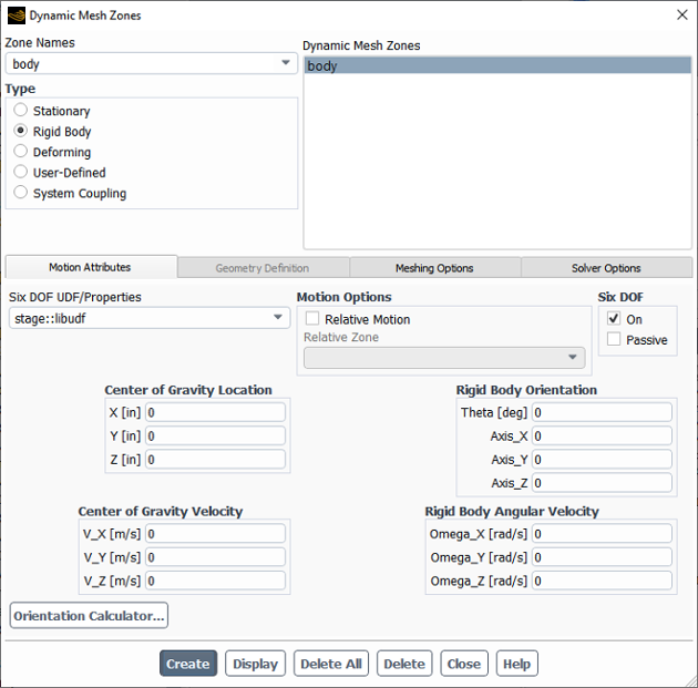
Select Rigid Body under Type in the Dynamic Mesh Zones dialog box (Figure 6.119: The Dynamic Mesh Zones Dialog Box) and click the Motion Attributes tab. Make sure that the On option in the Six DOF group box is enabled, and select the function name (for example, stage::libudf) from the Six DOF UDF/Properties drop-down list. Click Create then Close.
See
DEFINE_SDOF_PROPERTIES
for
details about DEFINE_SDOF_PROPERTIES functions.
After you have compiled (Compiling UDFs) your
DEFINE_CONTACT UDF, the name of the argument you supplied as the first
DEFINE macro argument will become visible and selectable in the
Contact UDF drop-down box of the Contact Detection
tab in the Options dialog box of Ansys Fluent.
To hook the UDF to Ansys Fluent, you will must first right-click the General branch of the tree and select Transient from the Analysis Type sub-menu.
![]() Setup → General
Setup → General ![]() Analysis Type → Transient
Analysis Type → Transient
Next, enable the Dynamic Mesh option in the Dynamic Mesh task page.
![]() Setup →
Setup → ![]() Dynamic Mesh →
Dynamic Mesh → ![]() Dynamic Mesh
Dynamic Mesh
Then, select the Contact Detection check box in the Options group box, and click the Settings... button to open the Options dialog box (Figure 6.120: The Options Dialog Box Showing the Contact Detection Tab).
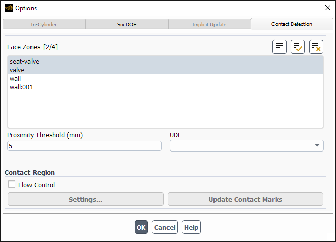
Select the function name (for example, contact_props::libudf) from the UDF drop-down list.
See
DEFINE_CONTACT
for details
about DEFINE_CONTACT functions.