The dynamic mesh model allows you to move the boundaries of a cell zone relative to other boundaries of the zone, and to adjust the mesh accordingly. The motion of the boundaries can be rigid, such as pistons moving inside an engine cylinder (see Figure 3.1: A Mesh Associated With Moving Pistons) or a flap deflecting on an aircraft wing, or deforming, such as the elastic wall of a balloon during inflation or a flexible artery wall responding to the pressure pulse from the heart. In either case, the nodes that define the cells in the domain must be updated as a function of time, and hence the dynamic mesh solutions are inherently unsteady. The governing equations describing the fluid motion (which are different from those used for moving reference frames, as described in Flows with Moving Reference Frames) are described in Dynamic Mesh Theory.
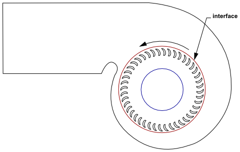
An important special case of dynamic mesh motion is called the sliding mesh in which all of the boundaries and the cells of a given mesh zone move together in a rigid-body motion. In this situation, the nodes of the mesh move in space (relative to the fixed, global coordinates), but the cells defined by the nodes do not deform. Furthermore, mesh zones moving adjacent to one another can be linked across one or more non-conformal interfaces. As long as the interfaces stay in contact with one another (that is, “slide” along a common overlap boundary at the interface), the non-conformal interfaces can be dynamically updated as the meshes move, and fluid can pass from one zone to the other. Such a scenario is referred to as the sliding mesh model in Ansys Fluent. Examples of sliding mesh model usage include modeling rotor-stator interaction between a moving blade and a stationary vane in a compressor or turbine, modeling a blower with rotating blades and a stationary casing (see Figure 3.2: Blower), and modeling a train moving in a tunnel by defining sliding interfaces between the train and the tunnel walls.